
Crystal checker

This circuit functions primarily as an oscillator and signal verification tool, utilizing a Colpitts oscillator configuration to generate oscillations at a desired frequency. The inclusion of Q2, which acts as a switching transistor, is critical for controlling the LED indicator. When the circuit is correctly oscillating, Q2 is activated, allowing current to flow through the LED, thereby providing a visual indication of the circuit's operational status.
The circuit can be tested using A3 HF crystals, which are designed for high-frequency applications. The "Go-No-Go" testing approach implies that the circuit will indicate whether the crystal is functioning properly (Go) or not (No-Go). The use of an untuned bulb rated at 6V and 40mA is a practical alternative for applications where a more straightforward visual indication is sufficient, replacing the LED for broader visibility.
The Colpitts oscillator's output is fed into a voltage multiplier circuit, which increases the output voltage suitable for driving the LED or bulb. This voltage multiplier is essential for ensuring that the LED receives enough voltage to illuminate effectively, especially when using lower voltage sources. Additionally, the rectifier in the circuit converts the AC oscillations produced by the oscillator into DC, which is necessary for powering the LED or bulb reliably.
In summary, this circuit serves as an efficient method for testing the operational integrity of high-frequency crystals, providing both visual feedback and adaptability for different output indicators.Use this circuit for checking fundamental oscillates, Q2 conducts and the LED lights. A3 HF crystals on a "Go-No-Go" basis. An untuned or 6V, 40mA bulb could be substituted for the Colpitts oscillator drives a voltage multiplier LED rectifier and a current amplifier. If the crystal.
Related Circuits
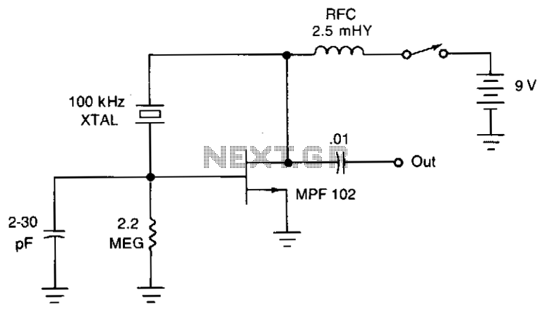
The JFET Pierce oscillator is stable and straightforward. It can serve as the clock for a microprocessor, a digital timepiece, or a calculator. With a probe connected to the output, it can function as a precise injection oscillator for...
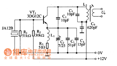
The 27MHz crystal oscillator circuit is illustrated in the figure. Resistors R1, R2, and R3 serve as biasing resistors, while capacitor C6 functions as a bypass capacitor. The voltage division circuit consists of capacitors C1, C3, C4, and C2,...
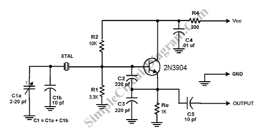
A Crystal Colpitts oscillator can be constructed using a parallel mode crystal and a transistor. The circuit is depicted in the accompanying figure. In this configuration, an inductance is utilized. The Crystal Colpitts oscillator is a type of electronic oscillator...
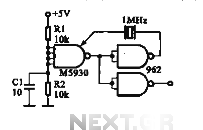
A crystal oscillator is implemented using a DTL (Diode-Transistor Logic) integrated circuit. The oscillation frequencies are 100 kHz and 1 MHz. The circuit consists of a gate circuit that generates a signal for the oscillator circuitry in DTL. The crystal...
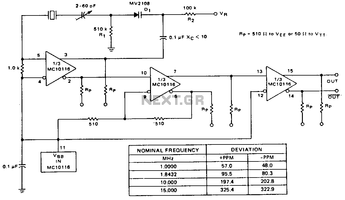
A voltage-variable capacitance tuning diode is connected in series with the crystal feedback path. Adjusting the voltage on the variable resistor (VR) changes the capacitance of the tuning diode, which in turn tunes the oscillator. The 510 kΩ resistor...
The OPB350 series liquid sensor is designed to operate with clear tubes of various outer diameters: 1/16 inch (1.6 mm), 1/8 inch (3.2 mm), 3/16 inch (4.8 mm), and 1/4 inch (6.3 mm). When integrated with output reference circuitry,...