
Three-phase square wave signal oscillator circuit
The circuit employs the CD4017 decade counter, which is capable of counting up to ten, but in this configuration, it is utilized as a senary (six-state) counter. The input clock frequency of 300 Hz allows the counter to cycle through its states at a rapid pace, producing output signals that can be used for various applications, such as driving motors or controlling other electronic devices.
The arrangement of diodes VD1 to VD9 and resistors R1 to R3 creates three three-input OR gates. These gates are crucial for combining the two 50 Hz three-phase signals, which are phase-shifted by 120 degrees. Each OR gate effectively sums the inputs, resulting in a single output that represents the combined signal. The outputs of these gates are designated as A, B, and C, which correspond to the three-phase signals required for the application.
The three-phase signals produced are essential for applications that require balanced loads, such as three-phase motors or power systems. The 120-degree phase difference between the signals ensures that the outputs are evenly distributed, which is critical for maintaining system stability and efficiency. The schematic representation in Figure 16-5 further illustrates the relationships between the components and the generated signals, providing a clear understanding of the circuit's functionality.
Overall, this configuration effectively demonstrates the use of a CD4017 counter in conjunction with OR gates to generate synchronized three-phase signals, showcasing its practical application in electronic systems.As shown in Figure 16-4, a CD4017 is connected as senary counter, and the input clock is 300Hz.VD1 ~ VD9, R1 ~ R3 form the three three-input OR gates, which can respectively get two 50Hz three-phase wave signal with 120 degrees phase difference. A, B, C can obtain three -phase signal, and it is shown in Figure 16-5.. 🔗 External reference
Related Circuits
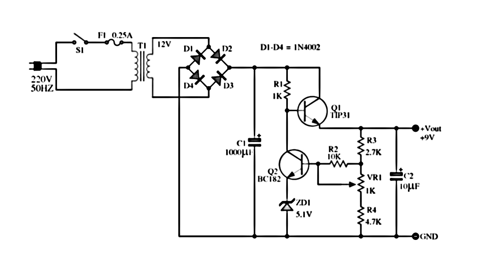
The power supply described utilizes a regulator composed of two NPN transistors. One transistor functions as the power regulator, while the other controls the output voltage. This power supply offers an adjustable output voltage range of 6-12 VDC. The...
This circuit operates at 36V with a current of 500mA on the front side, while it features a 36V charging capability on the back side. The brightness is comparable to that of a 240V light bulb, considering it is...
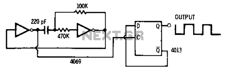
The 4013 pairs of D-type flip-flops in the astable multivibrator configuration are utilized as a binary divider output, generating an output frequency that is symmetrical, with a duty cycle of 50%. The 4013 integrated circuit contains two D-type flip-flops that...
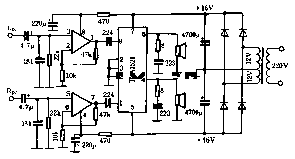
The first power amplifier circuit illustrated in Figure 5-88 utilizes the NE5532 operational amplifier, configured as a line amplifier, and features the TDA1521 power amplifier. This circuit operates with a dual power supply and eliminates the need for coupling...
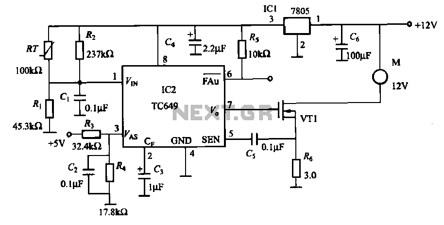
A motor is a heating device that can overheat, often due to accidents or overloads caused by excessive coil winding temperatures. The TC649 motor overheating protection and drive circuit, depicted in FIG. 1-9, utilizes an NTC thermistor (RT) positioned...
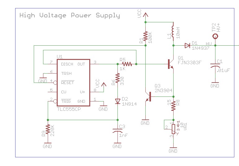
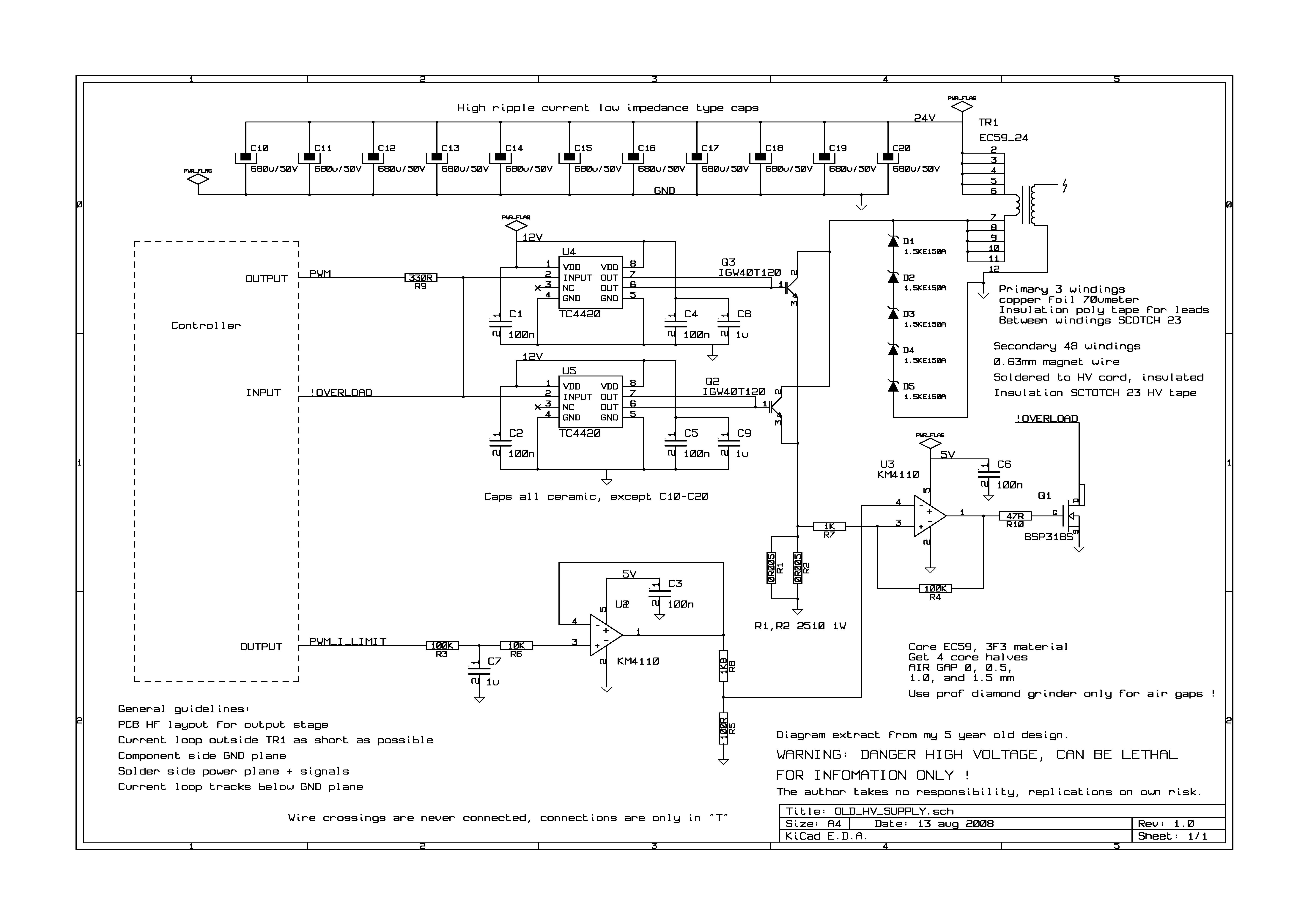
The design involves using a 555 timer as an oscillator in the high voltage power supply section. There is a query regarding the possibility of altering the design to utilize an output from a microcontroller to generate an oscillating...