
Cmos Piezo Driver Circuit

The use of a CMOS gate combined with a transistor buffer offers a robust solution for driving piezoelectric transducers. CMOS technology, known for its low power consumption and high noise immunity, provides a stable voltage level that can effectively control the operation of the transducer. The transistor buffer serves to amplify the signal generated by the CMOS gate, ensuring that the output can drive the transducer with sufficient current and voltage levels.
In a typical configuration, the CMOS gate can be employed to generate a digital signal from a microcontroller or other digital logic sources. This signal is then fed into the base of the transistor buffer, which may be configured as a common-emitter or common-collector amplifier depending on the required output characteristics. The transistor buffer amplifies the signal, providing the necessary drive capability to activate the piezoelectric transducer.
The piezoelectric transducer operates by converting electrical energy into mechanical energy and vice versa, making it suitable for applications such as sound generation, vibration, and sensing. The combination of the CMOS gate and transistor buffer not only ensures that the transducer receives the appropriate drive signals but also enhances the overall efficiency and performance of the system.
When designing this circuit, attention must be paid to the specifications of the piezoelectric transducer, including its impedance and required drive voltage. Additionally, the choice of transistor type (BJT or MOSFET) can influence the efficiency and speed of the driving circuit. Proper biasing and protection mechanisms, such as diodes, may also be incorporated to safeguard the circuit from voltage spikes and ensure reliable operation. Overall, this configuration presents a practical approach for effectively driving piezoelectric devices in various electronic applications. A CMOS-gate and transistor buffer can be used as an effective driver for a piezoelectric transducer. 🔗 External reference
Related Circuits
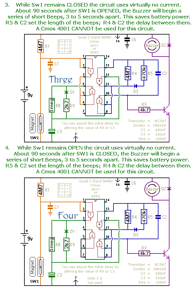
This document presents a collection of compact, self-contained alarm circuits. These circuits are designed to operate with a very low standby current, making them ideal for battery-powered applications. They can be triggered by both normally-open and normally-closed switches, while...
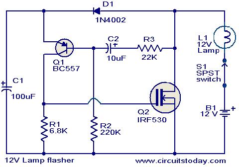
This circuit is a straightforward yet effective solution for flashing 12V lamps, particularly those utilized in automobiles. The flashing mechanism relies on transistor Q1 (BC557) and MOSFET Q2 (IRF530), with Q2 delivering the required drive for the lamp. The...
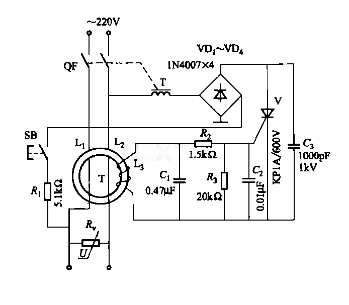
DBS-20 type leakage protection circuit The DBS-20 type leakage protection circuit is designed to detect and prevent electrical leakage, thereby enhancing safety in electrical installations. This circuit operates by monitoring the current flowing through the live and neutral conductors. When...
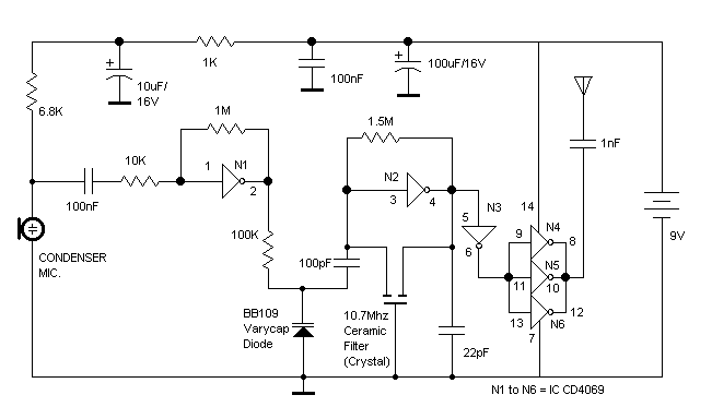
The RF oscillator using the inverter N2 and 10.7MHz ceramic filter is driving the parallel combination of N4 to N6 through N3. Since these inverters are in parallel, the output impedance will be low so that it can directly...
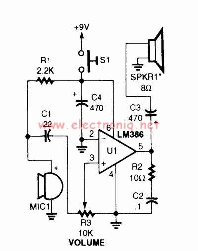
A voice amplifier can be designed using the LM386 power amplifier, which is intended for low voltage consumer applications. This simple circuit features variable gain and volume control. The gain is set internally to 20 to minimize the number...
There have been several requests for a quiz circuit, leading to the development of a four-input design that can be easily modified. This design utilizes four integrated circuits (ICs) and features four input circuits, four independent outputs, and a...
Warning: include(partials/cookie-banner.php): Failed to open stream: Permission denied in /var/www/html/nextgr/view-circuit.php on line 713
Warning: include(): Failed opening 'partials/cookie-banner.php' for inclusion (include_path='.:/usr/share/php') in /var/www/html/nextgr/view-circuit.php on line 713