
Coilless FM transmitter circuit
The described RF oscillator circuit utilizes an inverter (N2) in conjunction with a 10.7 MHz ceramic filter to generate a stable RF signal. The output from this oscillator is routed to a series of inverters (N4 to N6) connected in parallel through another inverter (N3). This configuration is advantageous as it lowers the output impedance, allowing for efficient driving of an aerial antenna that is designed to be 1/4th the wavelength of the operating frequency.
Given that the output from the inverters N4 to N6 is a square wave, it inherently contains multiple harmonic frequencies. Notably, the 9th harmonic of the fundamental frequency (10.7 MHz) is calculated to be 96.3 MHz, which coincides with the center frequency of the FM broadcasting band. This harmonic generation is a critical aspect of the circuit, as it enables the transmission of frequency-modulated signals within the designated FM band.
Additionally, the circuit includes an audio amplifier (N1) that processes audio signals from a microphone. The amplified audio signals are directed to a varicap (variable capacitance) diode. The functionality of the varicap diode is essential, as it allows for dynamic alteration of its capacitance in response to the audio signal levels. This change in capacitance modulates the frequency of the oscillator, effectively producing frequency modulation (FM) of the transmitted signal. The integration of these components facilitates the generation of an RF signal that is modulated with audio information, suitable for radio transmission applications.The RF oscillator using the inverter N2 and 10.7Mhz ceramic filter is driving the parallel combination of N4 to N6 through N3.Since these inverters are in parallel the output impedance will be low so that it can directly drive an aerial of 1/4th wavelength. Since the output of N4-N6 is square wave there will be a lot of harmonics in it. The 9th harmonics of 10.7Mhz (96.3Mhz) will hence be at the center of the FM band . N1 is working as an audio amplifier. The audio signals from the microphone are amplified and fed to the varycap diode. The signal varies the capacitance of the varycap and hence varies the oscillator frequency which produce Frequency Modulation. 🔗 External reference
Related Circuits
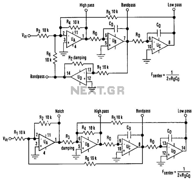
The classic state-variable (two-integrator) filter is well-known for its insensitivity to device parameter tolerances and its capability to provide three simultaneous separate outputs: high pass, bandpass, and low pass. These advantages often outweigh the requirement of a quad operational...
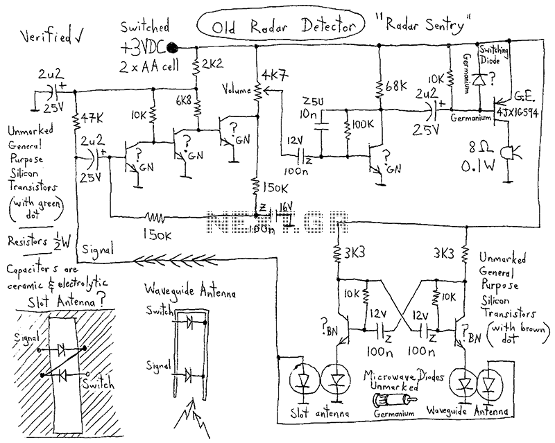
This device is a highly effective capacitive sensor. In North America, it is primarily utilized for detecting wooden beams behind drywall or plaster. This model is preferred over newer designs due to its reliability, as it does not frequently...
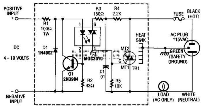
Rl limits input current while Ql acts as a current sink to protect IC1. D1 serves as a polarity protector. IC1 provides a triac output to trigger the main triac, TR1. The circuit consists of several key components that...

A preamplifier that operates on a single supply and is suitable for high-impedance crystal pickups is presented here. The circuit functions as a non-inverting AC amplifier, with the gain determined by the feedback resistor R4; a smaller R4 results...
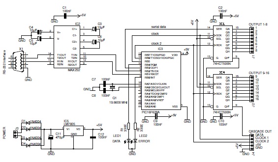
This basic PIC-based RS-232 serial interface can control up to 120 digital TTL outputs. The described circuit utilizes a PIC microcontroller to facilitate communication via the RS-232 protocol, which is a standard for serial communication. The interface primarily serves to...
High-voltage power supply circuit for fluorescent light power supply. Refer to that page for an explanation of the related circuit diagram. The high-voltage power supply circuit designed for fluorescent lights typically consists of several key components that work together to...