
code switching EPROM circuit
The 128K EPROM (27C128) is a non-volatile memory device that stores data in the form of binary digits. Each of the 16,384 addressable locations in the chip can hold one byte of data, leading to the total capacity of 128K bits. The architecture includes 14 address lines (A0 to A13), enabling direct access to each memory cell. The binary addressing scheme allows the ECM to read data by sending specific binary signals corresponding to the desired memory addresses.
For example, when the ECM sends a binary address to the EPROM, the address lines decode the input, activating the corresponding memory location. The data stored at that location is then outputted through the data lines. This process is essential for the ECM to retrieve operational parameters or calibration data necessary for engine management.
In contrast, the 27C010 EPROM expands this functionality with 17 address lines, allowing for a significantly larger memory capacity of 1 megabit. This increase enables the storage of more complex programs and data sets. When utilizing the 27C010, the same 128K code can be mapped to multiple address ranges. Accessing these ranges requires careful manipulation of the upper address lines (A14 to A16). By employing a switch mechanism, the ECM can be tricked into accessing different sections of the 27C010 while still operating under the assumption it is interfacing with a 128K EPROM.
For instance, if the ECM attempts to access address 0000h, setting A14 to 1 could redirect it to the 4000h to 7FFFh range of the 27C010. This method allows for a seamless transition between different memory banks without requiring significant changes to the ECM's operation. It is crucial to ensure that the data intended for access remains consistent across the various sections of the larger chip to prevent operational discrepancies.
In summary, the 128K EPROM and its larger counterpart, the 27C010, provide essential memory solutions for automotive applications, enabling efficient data management and retrieval through binary and hexadecimal addressing schemes. Understanding these principles is vital for engineers and technicians working with embedded systems in automotive technology.For this article, we will use the 128K EPROM (27C128 used in the 1986 to 1989 IROC-Zs with the 1227165 ECMs) as the basis for our discussion. This purpose of this article is to educate those on a little bit of binary and hexadecimal background, in order to understand what`s going on.
Binary numbers consist of 1`s and 0`s only. 1 = 1, 2=10, 3=11, 4 =100, 5=101 and so on. Here`s a simple charted example of one byte (8 bits) of data to explain better: The binary number 10101011 equals 171 in decimal. How did we do this We took the number 10101011 and entered the bits into the numbered chart (Going from right to left, start from 1 and double the value as you go left.
1, 2, 4, 8, etc. as shown on the top row. ) Then, wherever this is a 1 bit, add that number represented, then the next 1 bit and so on. So we added 128+32+8+2+1 to equal 171. What is 171 in hexadecimal Well, let`s leave it as binary. Hexadecimal is a 16 number base system. You would count 0, 1, 2, 3, 4, 5, 6, 7, 8, 9, A, B, C, D, E, F, 10, 11, 12, etc. Take the right side of the chart above. Add the 1`s together (8+2+1) = 11 in decimal, but B in hexadecimal. Remember 9, A, B, C represents 11 in decimal. We would then do the same on the left side, but here`s the trick. Use the SAME numbering convention as if you`re starting over on this section. You would not use 128, 64, 32, 16. Use 8, 4, 2, 1 again. Add the 1`s together (8+2) = 10 in decimal, but A in hexadecimal. So 171 = 10101011 in binary = AB in hexadecimal. Yes, we could always use the scientific calculator in Windows, sure, but in order to understand how this code switching works, take the time and convert some numbers to binary and hexadecimal. Then VERIFY with calculator to see if you`re correct. Let`s discuss the 128K EPROM chip, otherwise known as the 27C128 or equivalent. This chip holds 16384 address points with 1 byte of data each. 1 byte equals 8 bits of data (binary numbers equal 1 bit of data), multiplied by 16384, you get 131072 bits (or 128K bits) of total memory.
Remember the 16384 address points. The hexadecimal value of 16384 is 4000h (we will use h to signify that we are talking about a hexadecimal number). On an EPROM chip, this would be addresses 0000h to 3FFFh. There are 14 address lines in the 128K EPROM chip. A0-A13. Go ahead, figure that one out! Addressing is done via binary. Take the address lines and lets chart it out Now the good part. Switching of the code on a larger EPROM (or EEPROM) chip. Let`s use the 32-pin 27C010 chip, which is a 1-megabit chip. We could fit 8 times the code on a 1-megabit chip of the 128K bit chip. For this example, we`ll go ahead and put the same 128K code in the different sections of the 27C010 chip.
Code from 0000h to 3FFFh of the 27C128 would fit in 0000h to 3FFFh, 4000h to 7FFFh, 8000h to BFFFh, C000h to FFFFh, 10000h to 13FFFh and so on. But how would we access the different sections of the larger chip How would the ECM know It doesn`t.
We`re going to fool the ECM into thinking it`s accessing the same data via it`s addressing scheme. By manipulating the upper addresses (A14-A16 on the 27C010) manually, we can set the address to different (4000h at a time) sections via a switch of some sort. Let`s see how this works well, first off, the 27C010 uses 17 address lines (A0-A16) Since the 27C128 chip only has 14 address lines, Setting A14 to A16 to 0` would accomplish the same feat.
ECM wants to access 0000h, it would get 0000h. Theoretically, with an adapter, you could use a 27C010 chip and as long as the needed data resides at 0000h to 3FFFh, everything would be fine. With a switch, we`re going to set A14 to 1`. What does this do Changes the address dramatically. If the ECM is wanting to access 0000h and we set the A14 address bit to 1, the ECM would get data in the 4000h to 7FFFh section of the EPROM chip.
Why Do the math as above. Set the A16 to A14 address section to 2. ` Which would be 🔗 External reference
Related Circuits
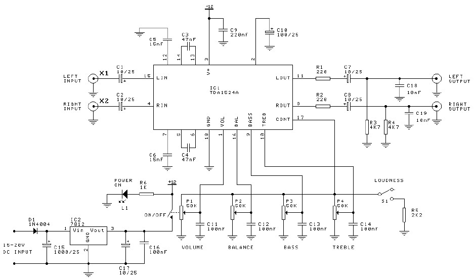
Preamplifier and tone control circuit based on the TDA1524A. The tone control circuit module is included in this preamplifier circuit, allowing for direct connection of the output channels to a stereo power audio amplifier circuit. This RIAA stereo preamplifier...
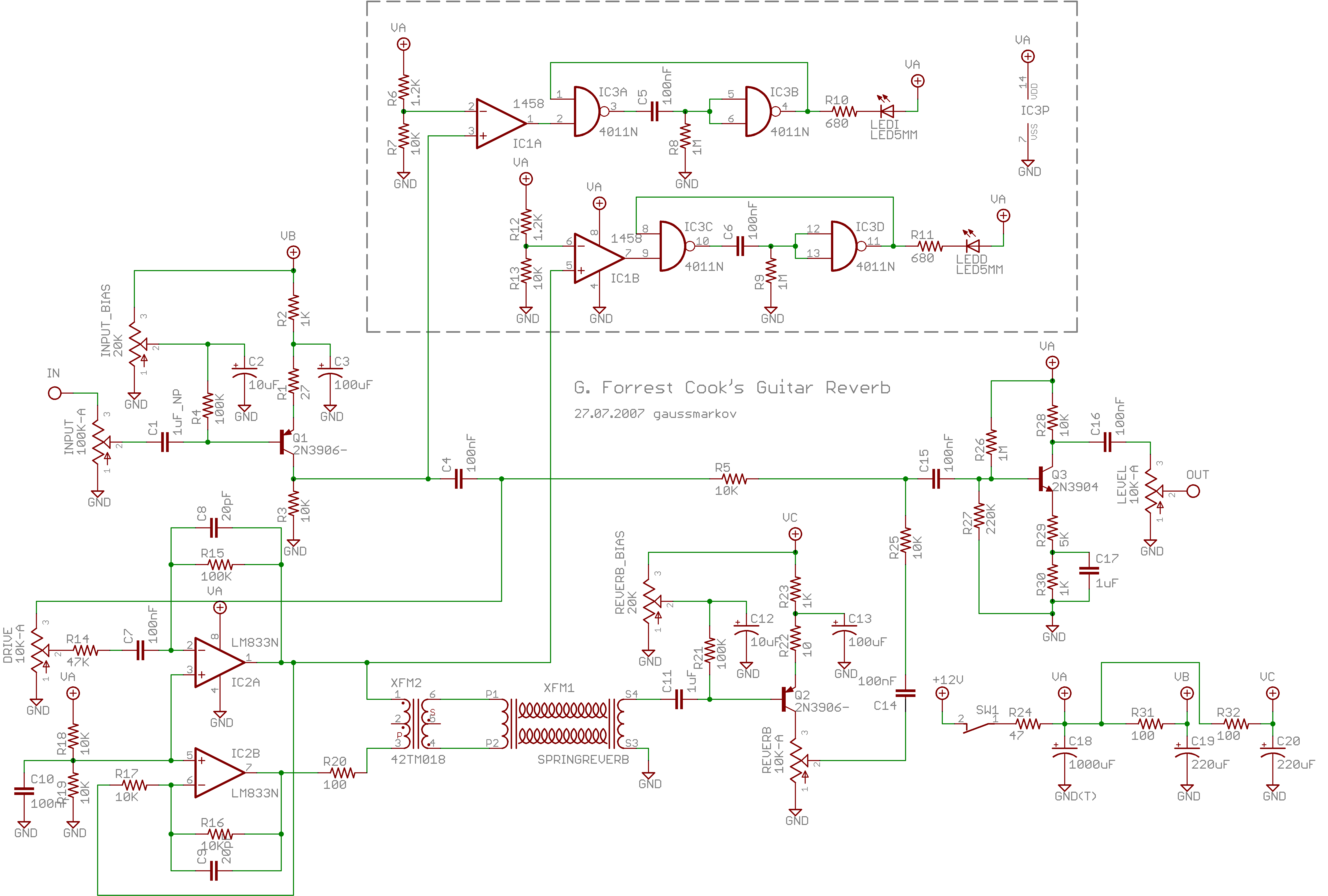
Spring reverb produces a clean and natural sound, often perceived as exceptionally good for a spring reverb. However, when the reverb springs are struck forcefully, they create explosive dub-like effects. Spring reverb is an analog sound processing technique that utilizes...
This circuit deactivates an amplifier or any connected device when a low-level audio signal at its input is absent for at least 15 minutes. By pressing P1, the device is powered on, supplying power to any appliance connected to...
In the first circuit, the BC548 transistor is configured as a Colpitts oscillator, with the frequency being adjusted through the use of a crystal. A high-quality crystal will produce high-frequency oscillations, and the output at the collector is rectified...
Hello everyone. I need some help. I have constructed a PWM and PPM circuit. The output is functioning smoothly, but I am experiencing some problems and I am not very experienced. The PWM (Pulse Width Modulation) and PPM (Pulse Position...
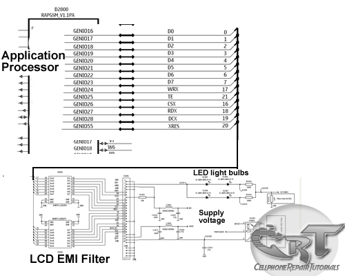
An LCD (liquid crystal display) is an electronically modulated optical device composed of multiple pixels filled with liquid crystals, arranged in front of a light source (backlight) or reflector to generate images in either color or monochrome. The block...