
how lcd display interface circuit works 20
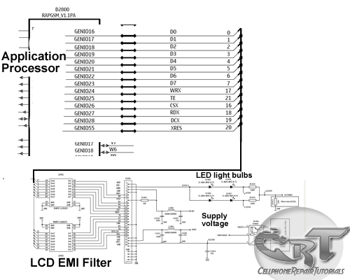
The LCD operates by manipulating liquid crystals in response to electrical signals, allowing for the control of light passing through the display. The application processor sends pixel data to the LCD driver, which interprets this data and controls the voltage applied to each pixel. The arrangement of pixels creates the desired image by selectively blocking or allowing light from the backlight to pass through.
The LED backlight provides the necessary illumination for the display. It is typically arranged in a series configuration, where multiple LEDs work together to achieve uniform brightness across the LCD screen. The backlight is crucial for visibility, especially in low-light conditions. The power supply circuit ensures that the voltage levels are stable and within the required range to prevent damage to the LCD and its components.
Electromagnetic interference (EMI) filtering is essential to ensure that external signals do not disrupt the operation of the LCD. This is typically achieved using capacitors and inductors strategically placed in the circuit. The filtering components help maintain signal integrity, ensuring that the data transmitted from the application processor to the LCD is clear and precise.
The schematic diagram for the LCD circuit in mobile phones typically includes not only the application processor and LCD connector but also the backlight driver circuit, power management components, and EMI filters. Each component is carefully placed on the printed circuit board (PCB) to optimize space and performance while minimizing interference and signal loss.
In summary, the LCD display circuit in mobile phones is a complex assembly that integrates various components to ensure optimal performance. The careful design of the circuit and the arrangement of components on the PCB are critical for achieving high-quality display output and user experience.An LCD -liquid crystal display is an electronically-modulated optical device made up of any number of pixels filled with liquid crystals and arrayed in front of a light source (backlight) or reflector to produce images in color or monochrome. The block diagram shows the LCD gets a data source from the application processor, so therefore LCD is bei
ng controlled by the application processor to produce a detail images, LED is a light emitting diode that can produce light, this light source of an LED is the one that reflect at the back of an LCD, without this LED light reflection on the back of an LCD it will result a black or dark screen displays. LCD also needs a power supply voltage to activate its liquid crystal arrays inside of it, so that is why a voltage supply is also very important for that matter.
An LCD Display Circuit Schematic diagram of a mobile phones below interprets how the whole circuitry of an LCD being connected and designed. A circuit start from an application processor that controls and sends data to LCD connector which where the LCD is being connected.
Before the data reach to the LCd connector it is being filtered for Electromagnet Interference protection. The LED light circuit and a power supply voltage is also provided for it is also work an important part on LCD circuit.
The picture below interprets the schematic diagram above on how each components layout are being mounted on a particular mobile phones printed circuit board. 🔗 External reference
Related Circuits
This tutorial explores a common digital concept using the NI Multisim software environment. It examines a four-bit counter that uses a 555 timer IC to generate the clock signal. This tutorial takes less than 30 minutes to complete and...
A sequential timer circuit device is utilized in various applications for initializing conditions during start-up or for activating test signals in sequences, such as in test equipment devices. The circuit diagram below illustrates a sequencer circuit with potential applications...
The intercom schematic provides a reliable communication line and is straightforward to construct. The circuit consists of an amplifier, two switches, and two loudspeakers. If additional stations (speakers) are desired, more switches can be incorporated into the circuit. The...
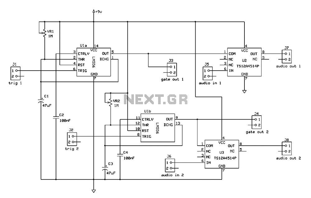
The Switchgate is a simple dual gate circuit based on a 556 timer configured in monostable mode, featuring a trigger input that activates two switches. The outputs of the monostables are also available individually. Recent research has led to...
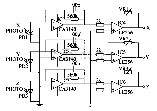
A semiconductor color sensor is designed to identify the color of an object using three photodiodes (PD1, PD2, PD3) and three corresponding color filters (X-PHOTO, Y-PHOTO, Z-PHOTO). Each photodiode is paired with a specific color filter: red (R), green...
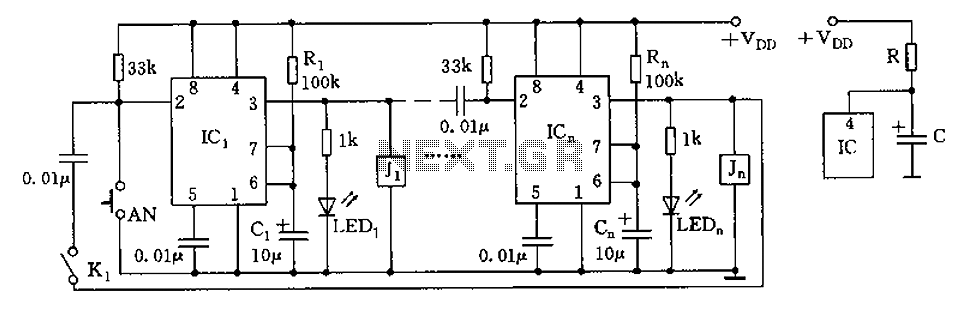
The circuit depicted in the figure is designed for multi-temperature testing, allowing for the switching of the thermocouple corresponding to the active channel. At the core of this design is a 555 timer configured in a monostable delay mode....
Warning: include(partials/cookie-banner.php): Failed to open stream: Permission denied in /var/www/html/nextgr/view-circuit.php on line 713
Warning: include(): Failed opening 'partials/cookie-banner.php' for inclusion (include_path='.:/usr/share/php') in /var/www/html/nextgr/view-circuit.php on line 713