
Two Simple Crystal Test Circuits

The first circuit described utilizes a BC548 transistor arranged as a Colpitts oscillator. This configuration is known for its ability to generate oscillations at a specific frequency, which can be finely adjusted by integrating a crystal into the circuit. The crystal acts as a frequency-determining element, and its quality significantly influences the performance of the oscillator. When a high-quality crystal is used, it facilitates the generation of stable and high-frequency oscillations. The output from the collector of the BC548 transistor is rectified by a germanium OA91 diode, which converts the alternating current (AC) signal into a direct current (DC) signal. This rectified output is then measured on a meter, where the degree of deflection corresponds to the oscillation amplitude. The output can be further adjusted using a preset resistor, allowing for precise control over the oscillation frequency.
The second circuit also employs a Colpitts oscillator, utilizing another BC548 transistor. In this configuration, the crystal continues to play a crucial role in determining the frequency of oscillation. However, the output is taken from the emitter rather than the collector, which allows for a different rectification approach. The output signal is full-wave rectified, which enhances the efficiency of the conversion process. The resulting small DC bias produced by this rectification is sufficient to activate a second BC548 transistor. This transistor serves as a switch, controlling the current flow to an LED. When the second BC548 is activated by the DC bias, it allows current to pass through the LED, causing it to illuminate. This design effectively demonstrates the interaction between oscillators and active components in a circuit, showcasing the practical applications of frequency control and signal modulation in electronic systems.In the first circuit, above the BC548 is wired as a colpitts oscillator, the frequency tuned by insertion of a crystal. A good crystal will create high frequency oscillations, the output at the collector is rectified by the germanium OA91 diode and a deflection will appear on the meter.
Thw more active the crystal, the higher the output deflection which may be adjusted with the preset. The next circuit uses a working crystal again used to control the frequency of a colpitts oscillator. This time the output from the oscillator is taken from the emitter and is full wave rectified, the small dc bias will then directly cause the second BC548 to light the LED.
🔗 External reference
Related Circuits
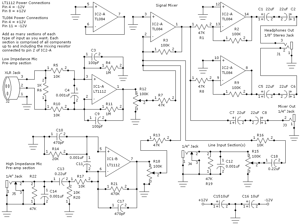
This weblog focuses on electronic circuit schematics, PCB design, DIY kits, and diagrams for various electronic projects. It features a mixer that demonstrates how to create microphone pre-amplifiers suitable for both low and high impedance microphones. The design utilizes...
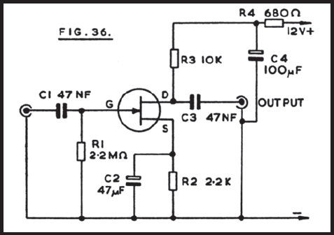
Figure 36 illustrates the circuit of a preamplifier featuring a high impedance input and an output circuit designed for coupling to a main amplifier. This configuration is particularly advantageous for applications such as amplifying the signal from a crystal...
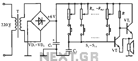
The circuit includes resistors Rp1 to Rp13, which serve dual purposes: they scale the resistance for the keyboard and function as timing resistors for the oscillator. Capacitor C2 acts as a wide discharge capacitor, while switches S1 to S13...

A flip-flop, functioning as an astable multivibrator, can be utilized to generate timing signals in music applications such as a metronome. This can be achieved by adjusting the transistor bias resistor with a value of 100k. The astable multivibrator configuration...
SEL2411AA is a sub-package of SEL2410. For a detailed description, please refer to SEL2410. The datasheet for SEL2411AA can be downloaded from the link provided below. By Pericom Semiconductor Corporation. The SEL2411AA is a specialized electronic component that serves as...
The project involves developing a 12W power amplifier circuit into a fully assembled hard-wired unit. This will require a design cycle and development sequence that includes analysis, simulation, printed circuit board (PCB) layout, board population, hard soldering, and testing....