
Solid State Relay Circuit Circuit
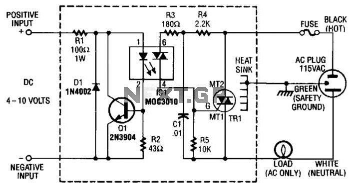
The circuit consists of several key components that work together to ensure safe operation and effective control of a load using a triac. Resistor Rl is strategically placed to limit the input current, thereby preventing excessive current from flowing into the circuit, which could potentially damage sensitive components. The current sink Ql, typically a bipolar junction transistor (BJT) or a field-effect transistor (FET), plays a critical role in protecting the integrated circuit IC1 by diverting excess current away from it. This configuration helps maintain the integrity of IC1, ensuring it operates within its specified limits.
Diode D1 functions as a polarity protection device, safeguarding the circuit against reverse voltage conditions that could occur if the power supply is connected incorrectly. This diode allows current to flow in only one direction, thereby preventing damage to the downstream components when a reverse polarity situation arises.
IC1 is designed to provide a triac output, which is essential for controlling AC loads. The triac output is used to trigger the main triac, TR1. The triac TR1 is capable of handling higher voltages and currents, making it suitable for switching applications in AC circuits. When IC1 activates TR1, it allows current to flow through the load, effectively controlling its operation based on the input conditions.
In summary, this circuit exemplifies a robust design that incorporates current limiting, protection against reverse polarity, and effective control of AC loads through triac switching. Each component serves a specific purpose, contributing to the overall reliability and functionality of the system. Rl limits input current while Ql acts as a current sink to protect IC1. D1 serves as a polarity protector. IC1 provides a triac output to trigger the mam triac, TR1. 🔗 External reference
Related Circuits
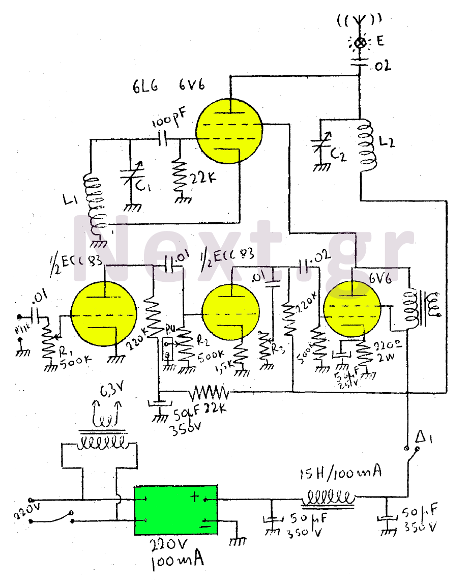
This circuit features a wearer assembly that includes a single lamp, either a 6V6 or 6L6, functioning as both an oscillator and an output amplifier. Coil L1 serves as the medium wave oscillation coil, while coil L2 is composed...
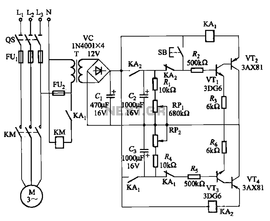
The circuit illustrated in Figure 3-79 consists of two delay circuits. The RPi adjustment potentiometer and RP2 can be modified to control the duration of the motor operation, allowing for arbitrary adjustments within a specified time frame. The circuit comprises...
This series-feedback configuration of compounds provides a high input impedance and stable, wide-band gain video amplifier suitable for general-purpose applications. It features low capacitance and high impedance. The described video amplifier circuit utilizes a series-feedback topology to achieve high input...
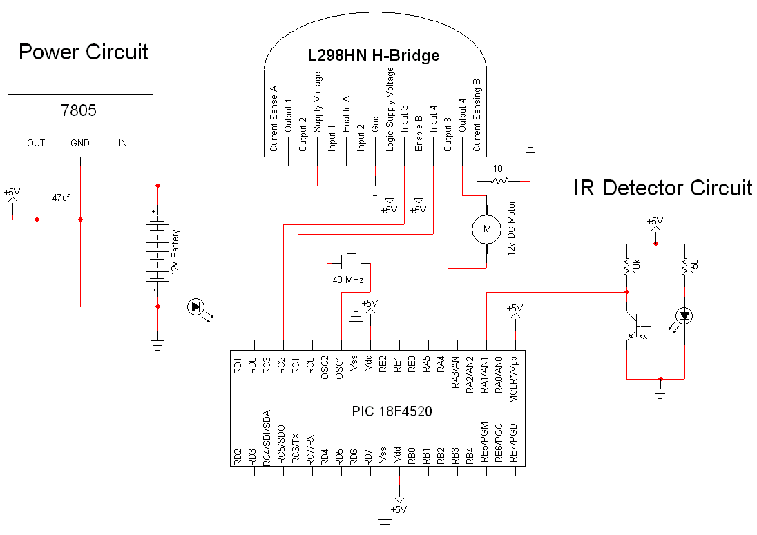
The simple motor optical encoder circuit is not particularly difficult; however, it requires careful verification to ensure all connections are correct before initial operation. The primary components utilized in the circuit include the 7805 voltage regulator, the PIC18F4520 microcontroller,...
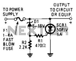
Many modern devices have shutdown circuits that are designed to remove power from the device when the voltage rises above a predetermined threshold. This circuit blows a fuse to protect the device under power. Shutdown circuits are critical components in...
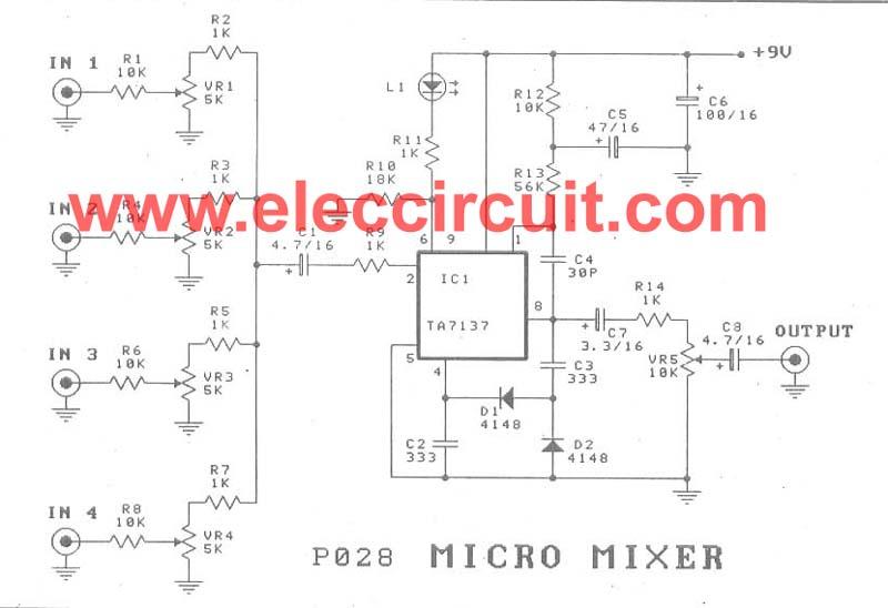
A micro mixer circuit is designed to be simple, affordable, compact, and versatile. This circuit can mix up to four input channels, including microphone signals, FM tuners, AUX, and other signals, as illustrated in Figure 1. The operation begins...
Warning: include(partials/cookie-banner.php): Failed to open stream: Permission denied in /var/www/html/nextgr/view-circuit.php on line 713
Warning: include(): Failed opening 'partials/cookie-banner.php' for inclusion (include_path='.:/usr/share/php') in /var/www/html/nextgr/view-circuit.php on line 713