
Four-Output Filter Circuit
The state-variable filter design employs a dual integrator configuration that enhances flexibility in signal processing applications. The three outputs—high pass, bandpass, and low pass—are achieved through the careful selection of feedback and feedforward components, enabling precise control over the filter characteristics. The modification that uses amplifier UD allows for a bandpass output that maintains a consistent peak gain, which is particularly beneficial in applications where gain stability is critical, such as audio processing or communication systems.
The notch filter output, achieved through the specific configuration of resistor R6, introduces additional utility by allowing unwanted frequency components to be attenuated without affecting the desired signal paths. This feature is advantageous in scenarios where noise suppression is necessary.
The relationship between the Q factor and the gains of the notch and bandpass outputs is crucial for achieving the desired filter response. The unity gain condition simplifies the design process, ensuring predictable behavior across various operational conditions. The resonant frequency, determined by the product of resistance R0 and capacitance CQ, can be adjusted dynamically, allowing for real-time tuning of the filter's response. The use of a monolithic network for resistance R0 not only conserves board space but also enhances reliability by minimizing the number of discrete components.
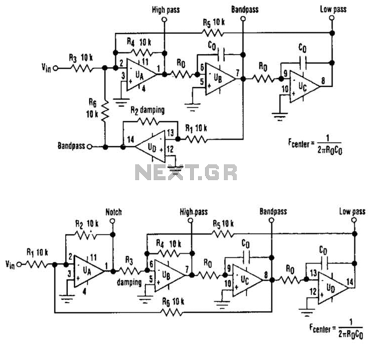
Incorporating analog multipliers in series with the integrators offers further versatility, enabling the implementation of complex filter responses and adaptive filtering techniques. This capability is particularly relevant in modern signal processing applications, where the ability to adjust filter parameters on-the-fly can significantly improve performance. Overall, the state-variable filter's architecture provides a robust solution for a wide range of electronic filtering needs, balancing performance, stability, and flexibility. The classic state-variable (two-integrator) filter (see Fig. A) is famous for its insensitivity to device parameter tolerances, as well as its ability to provide three simultaneous separate outputs: high pass, bandpass, and low pass. These advantages often offset the fact that a quad operational amplifier is needed to implement the circuit.
A modification of the classic scheme that applies the input voltage via amplifier UD, rather than UA provides a bandpass output with a fixed peak gain that doesn`t depend on the Q of the filter. It was found by using that configuration, a fourth notch-filter output can be obtained if - R6 (see Fig.
B). If R, -R^ = R2, the gains of both the notch and bandpass outputs are unity, regardless of the Q factor, as determined by R3, Rl, R2, R4, R5, and R6. The resonant (or cutoff) frequency is given by, - 1/R0 x CQ. Depending on the capacitor values and frequency, resistance R0 might also share the same monolithic network for maximum space economy.
As with the classic configuration, resonant frequency can be electrically controlled by switcliing resistors R0, or by using analog multipliers in series with the integrators. 🔗 External reference
Related Circuits
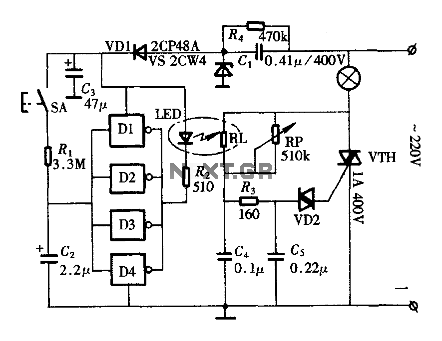
The lighting controller depicted in the figure features a gradual dimming function that prevents sudden brightness changes, which can irritate the human eye and potentially cause damage due to inrush currents. The circuit design includes a six-stage CD4069 inverter...
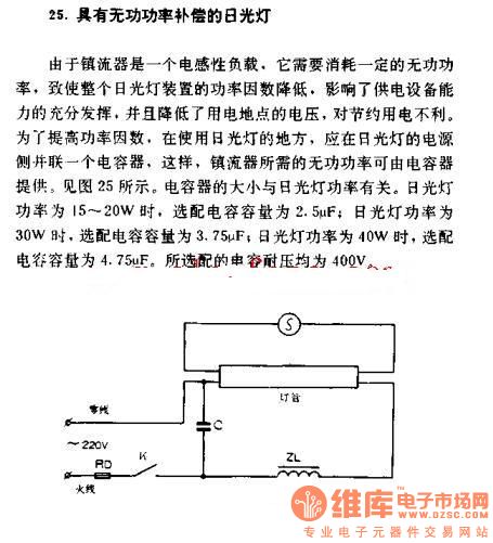
The fluorescent lamp with reactive power compensation operates with a ballast that acts as an inductive load. This inductive load requires reactive power, which leads to a decrease in the power factor of the fluorescent lamp. A lower power...
The electronic switch consists of the CK-4 type magnetic control switch and the components VT1, R1, and R2. When the bathroom door is closed, the permanent magnet ZT and the reed switch GA come into proximity, which separates the...
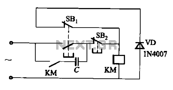
An AC contactor switch, when used with DC or pulse DC excitation, can minimize short circuit and core power consumption. This results in a significant reduction in the power consumption of the electromagnet, which can eliminate noise and reduce...
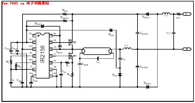
The IR2156 provides a cost-effective solution for fluorescent electronic ballasts. It integrates features such as lighting tube error protection and a programmable working frequency, which includes warm-up, lighting, and continuous operation of the ballast. The IR2156 is a highly integrated...
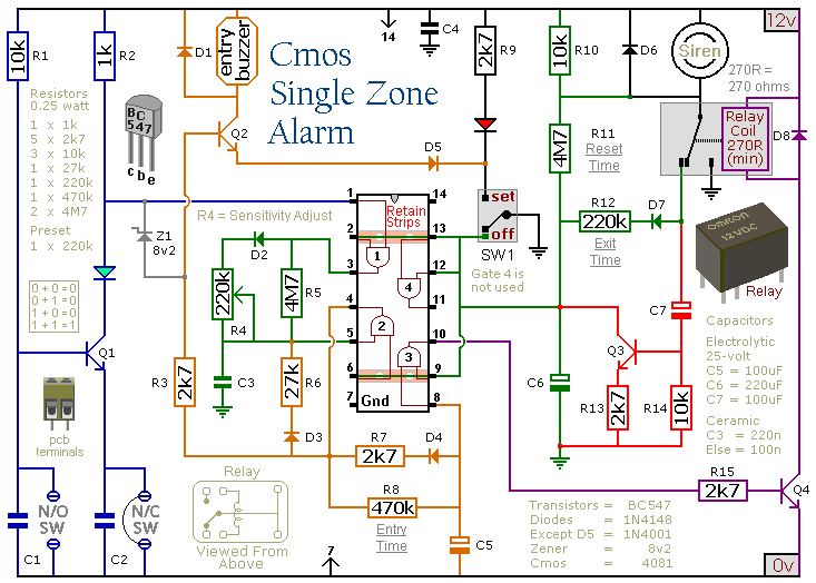
This circuit features automatic exit and entry delays, a timed bell cut-off, and a system reset. It accommodates both normally-open and normally-closed switches, making it compatible with various input devices such as pressure mats, magnetic reed contacts, foil tape,...
Warning: include(partials/cookie-banner.php): Failed to open stream: Permission denied in /var/www/html/nextgr/view-circuit.php on line 713
Warning: include(): Failed opening 'partials/cookie-banner.php' for inclusion (include_path='.:/usr/share/php') in /var/www/html/nextgr/view-circuit.php on line 713