
ColonBlow robot

The autonomous robot design emphasizes a streamlined approach to ball collection and goal scoring. The choice of materials, such as laser-cut acrylic and masonite, provides a lightweight yet sturdy framework, optimizing the robot’s overall performance. The integration of a foam core funnel serves to guide the balls effectively, minimizing the risk of jams during collection. The use of a door motor as an electro-mechanical switch enhances the control over the ball release mechanism, ensuring that balls are only released at the appropriate times.
The chassis design, featuring strategically placed caster wheels and a low center of gravity, contributes to stability during movement, allowing the robot to navigate quickly across the playing field. The placement of reflective object sensors is critical for maintaining alignment with the tape markings, facilitating precise movement and enhancing the robot's ability to follow predetermined paths. The adjustable mounting for these sensors allows for fine-tuning during testing phases, ensuring optimal performance.
Incorporating a microcontroller board and well-defined circuit paths ensures that the robot can process sensor inputs and control motors effectively, enabling real-time adjustments based on environmental feedback. Overall, the design prioritizes efficiency, speed, and adaptability, making it well-suited for competitive scenarios where quick decision-making and rapid execution are essential. The combination of mechanical ingenuity and electrical design creates a robust autonomous system capable of achieving its objectives while minimizing potential errors during operation.Our strategy was based on our ability to traverse complex, tape ridden terrain in the most efficient way possible: with superior speed. Even though we only went for goal #1, which was the lowest scoring goal, by acting quickly and finishing the game early, we hoped to limit the other team`s points.
Our mechanical and electrical designs were cen tered around our need for speed. We designed an autonomous robot that implemented a simple strategy to collect balls, hold them, and release them into goal #1. To collect balls, we placed a piece of foam core in the front of our robot to depress the ball request button.
As each ball dropped from the dispenser onto our robot, a funnel-like device channeled the balls into a hole, which led to a PVC pipe with a door motor acting as an electro-mechanical switch to prevent balls from leaving our robot. Our robot`s chassis consisted of a -thick piece of laser-cut acrylic (10 x 3 ) and a 1/8 -thick piece of laser-cut masonite (10 x 10 with fillets).
We placed the front edge of the acrylic piece two inches from the front edge of the masonite, which was also the front edge of our robot. This decision was based on our desire to place the drive wheels closer to the front of our robot rather than in the middle.
To provide our robot excellent stability while driving, we placed two spherical caster wheels at the back side of our robot. We placed these two casters 4. 67 apart center-to-center, which was long enough for stability, yet not significantly long to prevent our robot from moving too slowly at a given duty cycle.
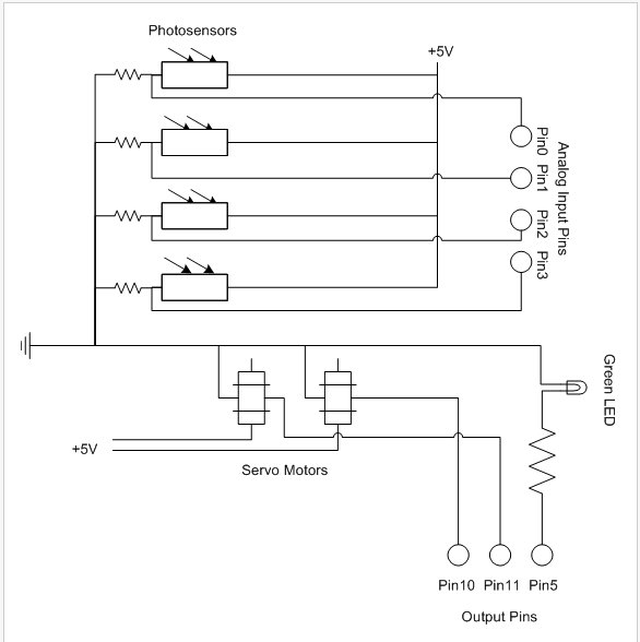
To track the various pieces of tape on the playing fields, we implemented a set of three QRB1134 reflective object sensors. Each adjacent pair of tape sensors was placed 0. 5625 apart center-to-center based on this measurement of the tape`s width. We desired to have only the middle tape sensor activated while traveling in a perfectly-straight line.
To provide our robot a precisely-manufactured part on which to mount our tape sensors, we used a 1/8 -thick laser-cut piece of masonite. To provide our robot greater robustness in dealing with the possibility of encountering the playing fields` walls, we implemented four QRB1134 reflective object sensors, one at each corner of our robot.
To allow for tweaking the direction and location of these proximity sensors, we designed our masonite chassis to have L-shaped holes at each of the four corners, with the width and/or diameter of these holes slightly larger than the width/diameter of the tape sensor slots (about 0. 15 ). As each ball dropped from the ball dispenser onto our robot, it fell onto a funnel made from foam-core.
The funnel was sloped in two different directions to prevent balls from getting stuck en route to our PVC pipe and ball release mechanism. We cut a hole at the nadir of our funnel with a diameter slightly larger than the ball`s diameter of 1.
75 . To attach the funnel to our robot, we used some electrical tape instead of hot glue to allow us the ability to tweak various components inside our robot. We collected five balls at each trip to the ball dispenser because our PVC pipe could hold five to six balls without the possibility of balls getting stuck in the hole of our funnel.
To provide an electro-mechanical ball release mechanism, we drilled a hole on the top surface of the PVC pipe near the end of the pipe. A door motor was placed directly above this hole, which opened for releasing balls and closed for preventing balls from leaving our robot at inappropriate times.
To elevate the door motor above the PVC pipe, we designed two identical 1/8 -thick pieces of masonite with slots for the door motor`s mounting holes and placed this on both sides of the PVC pipe. To adequately incorporate our electrical circuits and E128 microcontroller board, we laser-cut several sets of four holes through which we mounted various circuits.
In addition, a 🔗 External reference
Related Circuits
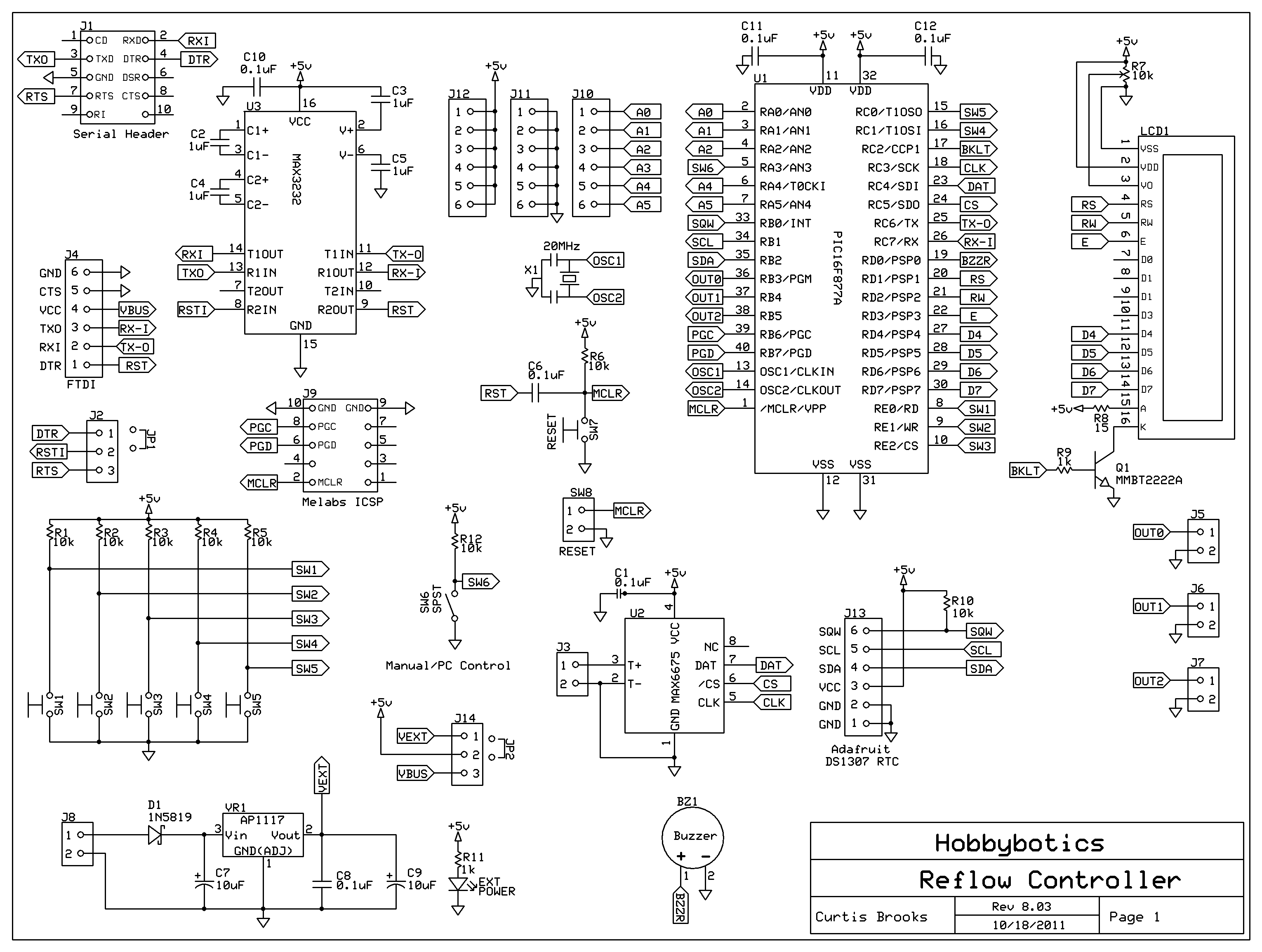
Introduction to the Reflow Process and PID Controller Circuit Documentation. This document discusses the benefits of using Surface Mount Devices (SMD) in circuit design, highlighting advantages such as reduced size and cost compared to traditional through-hole components. The reflow soldering...
When the 36 kHz infrared light emitted by the LEDs is reflected off an object, one of the receiver modules is activated. The PIC16F84 microcontroller then directs the robot to avoid the object by reversing one of the motors. The...
Cellphone Operated Land Rover (Mobile Phone Operated Robot). In this project, the robot is controlled by a mobile phone that makes a call to the mobile phone attached to the robot. The cellphone operated Land Rover project involves the design...
The Line Following Robot sensor, also known as a surface scanner for robots, is a compact, stamp-sized infrared proximity detector that operates within a short range of 5-10 mm. It is based on a standard reflective opto-sensor, the CNY70...
The individual has been engaged in garden railroading for just over a year, utilizing skills from various hobbies. They have designed and built two scratch-built bridges and nearly 100 trestle bents to support a 200-foot main line. Their interests...
The PhytoBot is a semi-intelligent plant that reacts to external stimuli, specifically light intensity and light location, mimicking the behavior of a phototropic plant. It is designed as an interactive artwork intended for prolonged operation. The motivation behind this...