
robotics reflow controller
The reflow soldering process is a critical technique in electronics manufacturing, particularly for assemblies that utilize SMD components. This process involves applying solder paste to the pads of a printed circuit board (PCB) where SMD components will be placed. After placement, the assembly undergoes a heating phase, which allows the solder to melt and form reliable electrical connections.
A Proportional-Integral-Derivative (PID) controller is often integrated into the reflow process to maintain precise temperature profiles throughout the heating cycle. The PID controller continuously monitors the temperature and adjusts the heating elements to ensure that the solder reaches the optimal melting point without overheating, which could damage components or the PCB itself.
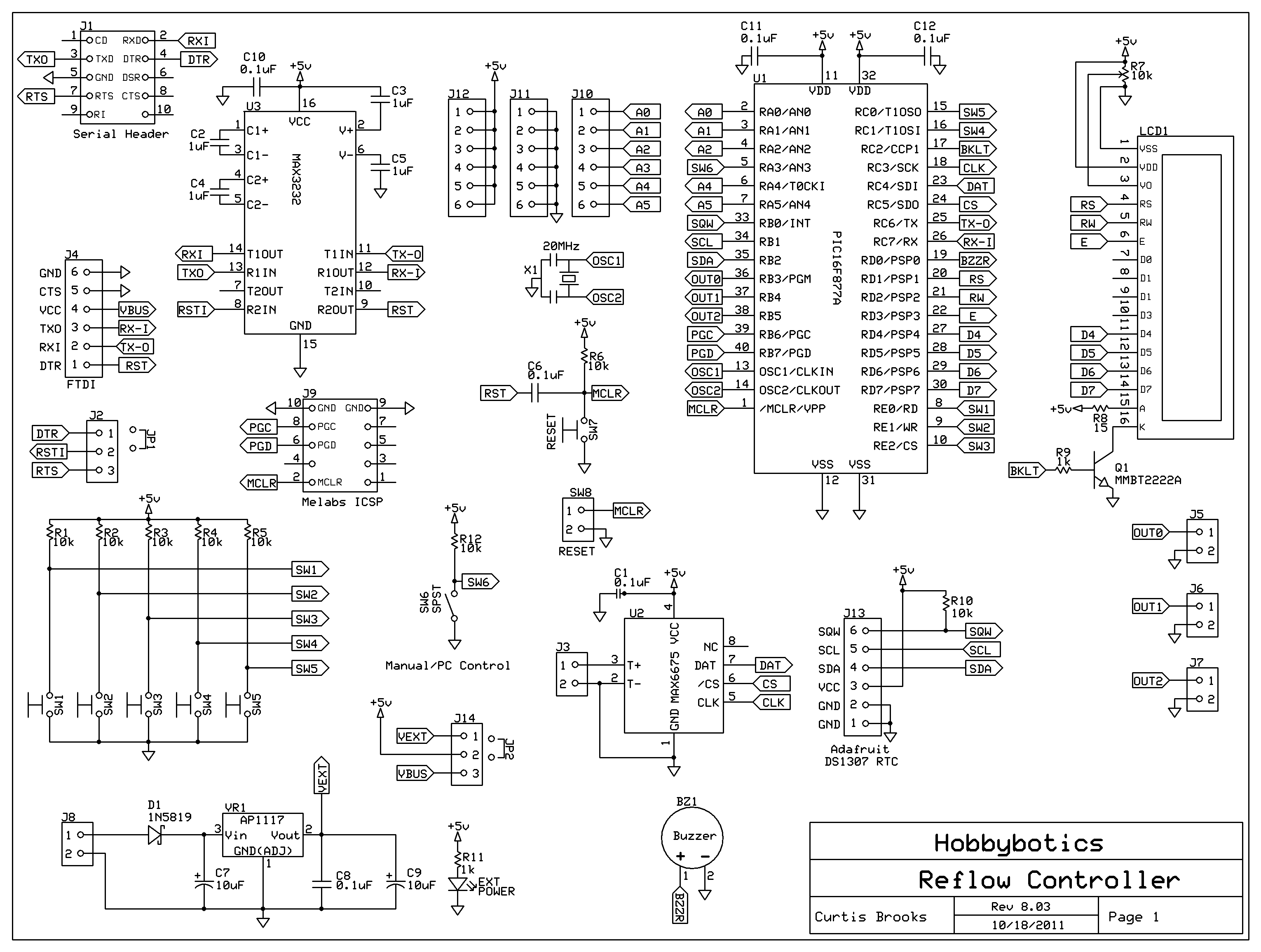
The documentation for building a PID controller circuit for a reflow oven typically includes schematics, component lists, and firmware instructions. The schematic should clearly outline the connections between the microcontroller, temperature sensors, and heating elements. Additionally, the firmware must be programmed to implement the PID control algorithm, which requires tuning of the proportional, integral, and derivative parameters to achieve the desired response.
In conclusion, the integration of SMD components and the implementation of a PID controller in the reflow process significantly enhance the efficiency and reliability of electronic assemblies. Understanding these concepts is essential for modern electronics design and manufacturing.Introduction The Reflow Process What is PID Controller Circuit Documentation Build It Firmware Software Conclusion Related Links References Disclaimer Introduction A while ago I decided to start designing my circuits using Surface Mount Devices (SMD). There are many advantages to using SMD components over through-hole components. Some of the major advantages are size and cost.. 🔗 External reference
Related Circuits
No description available. More: Q1, Q2: Standard-Transistoren D1: SB130 Q3: RFD 15 N 05 IC1A: CD4011B (if SMD) IC1B: detto The provided components suggest a basic electronic circuit that incorporates both transistors and integrated circuits, along with a diode. The circuit...
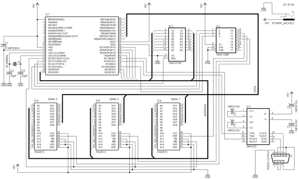
A RAM memory extender has been designed for PIC microcontrollers. This circuit incorporates various logic integrated circuits (ICs) and SRAM memory modules to enhance the data memory capacity of a PIC microcontroller. The designer has also supplied source code...
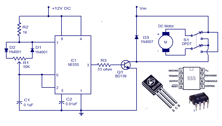
This weblog discusses electronic circuit schematics, PCB design, DIY kits, and electronic project diagrams. A simple DC motor controller circuit utilizing the NE555 timer is presented. Several DC motor speed control circuits are explored, with this being the first...
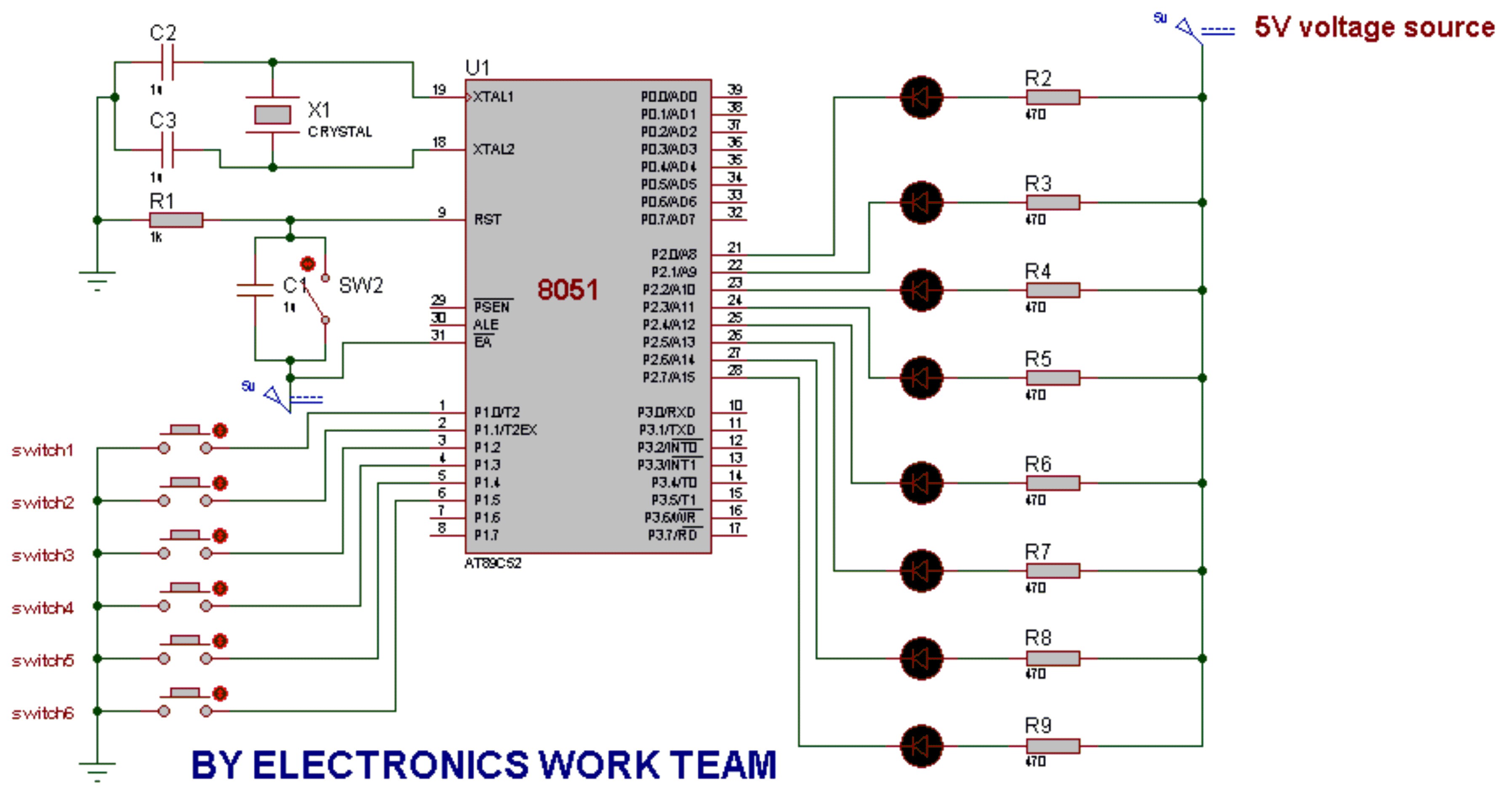
This post discusses the fundamental operation of the 8051 microcontroller using LEDs. The LEDs are connected to the P2 port, while six switches are connected to the P1 port of the 8051. By pressing various switches, the LEDs will...
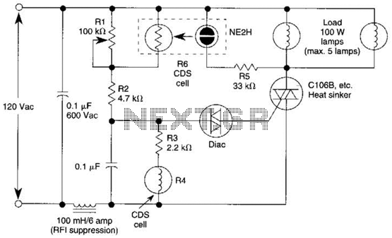
A neon bulb and a CdS photocell are enclosed in a light-tight enclosure to form an optocoupler. A diac/triac combination is employed to create a snap-switch effect. A second CdS photocell serves as the primary sensor. As darkness approaches,...
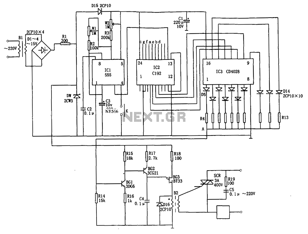
The automatic conversion circuit for wind speed control is depicted in Figure 10. This circuit consists of a clock signal generator (IC1), a counter (IC2), a decoder (IC3), a synchronous phase shifting circuit (BG1, BG2, BG3), a thyristor control...