
Color Mirror Screw Project

For the monochrome display, a row of 3 mm diameter red LEDs will be stacked vertically, with a diffusing material in front to ensure uniform light distribution. The screw's width is 4.75 inches, resulting in a horizontal resolution of approximately 40 lines (4.75 inches = 121 mm; 121 mm / 3 mm = 40). The LED row can be masked to create a slot about 1.5 mm wide, increasing the resolution to approximately 80 lines. Using 3 mm LEDs stacked vertically in alternating colors would complicate the use of diffusing material due to the distance between colors. The chosen solution involves larger 5 mm LEDs mounted on a separate chassis, with 0.75 mm diameter fiber optic cables connecting each LED to the light source box, where the fibers will be arranged vertically in alternating colors. The light source box height is designed to be about 20% taller than the screw, resulting in a height of approximately 4.2 inches (107 mm). A total of 144 fibers will be utilized (48 per color), potentially eliminating the need for diffusing material. This configuration offers several advantages: a significantly brighter image due to the use of super-bright LEDs, a compact light beam that negates the requirement for a diffuser, and a beam width of only 0.75 mm, which allows for a horizontal resolution of 170 lines.
Samples of LEDs and fiber optic cables have been ordered to experiment with attachment methods. A light meter will be employed to assess the efficiency of these connections. Preliminary findings indicate that the light entering the fiber is dependent on the fiber's cross-sectional area. With 0.75 mm fibers, the area is approximately 0.44 sq mm, while the face area of the 5 mm LED is around 19 mm. This results in roughly 2.3% of the LED's light entering the fiber cable. However, it has been observed that a single LED can illuminate at least 12 fibers (as they are bundled in groups of 12). Concerns remain regarding the brightness of the image projected onto the mirror screw. Potential solutions include the use of small lenses positioned in front of each LED to enhance light transmission.
The schematic for this project will include the following components:
1. **1200 RPM Synchronous Motor**: This motor will drive the screw mechanism, ensuring smooth rotation at the specified RPM.
2. **LED Configuration**: A combination of 5 mm LEDs arranged in rows for red, blue, and green colors, with a focus on maximizing brightness and minimizing the need for diffusing materials.
3. **Aurora Converter**: This device will convert video signals into the appropriate format for driving the LEDs, ensuring that the display can show both monochrome and color images.
4. **Fiber Optic Cables**: 0.75 mm diameter fibers will connect the LEDs to the light source box, with a total of 144 fibers organized to optimize color output.
5. **Light Source Box**: A custom enclosure designed to accommodate the fiber optics and LEDs, with a height of 4.2 inches to ensure proper alignment with the screw.
6. **Attachment Mechanism**: A method to connect the fiber optic cables to the LEDs, which may include the use of lenses to improve light coupling efficiency.
This comprehensive setup aims to create a visually striking display capable of showcasing both monochrome and color images effectively, with careful consideration given to the optical design and component arrangement.This would require a 1200 rpm synchronous motor and a light source, which would be made of a row of LEDs, arranged vertically, and located about 6 inches from the screw. My plan was enclose it in a clear plastic cabinet so all the components would be visible. Later, I had discussions with Darryl Hock about the possibility of making the mirror screw display color images.
He said that he could make a custom Aurora converter, which would output red, blue and green 60 line video signals. At that point I decided that the display at the museum would be both mono (orange) and in color. The image would display all three colors simultaneously, not sequentially as in the Baird mechanical color system of the 20s.
The light source would have a set of LEDs for each primary color: red, blue and green. Video from the Aurora converter would be amplified and used to drive each set of LEDs. With a mono display, a row of 3 mm diameter red LEDs can be stacked on top of each other, with a diffusing material in front to make the light more uniform. Since the screw we have is 4. 75 inches wide, the 3 mm width of the LEDs would result in a horizontal resolution of about 40 lines (4.
75 inches = 121 mm. 121/3 = 40). However, the LED row can be masked to make a slot about 1 1/2 mm wide, which would result in about 80 lines of resolution. If 3 mm LEDs were used, stacked vertically with alternating red, blue and green LEDs, it would be very difficult to use a diffusing material to even out the color (red LEDs would be 9mm apart, etc.
). The solution I have chosen is to use larger, 5 mm LEDs located on a separate chassis, with. 75 mm diameter fiber optic cables going from the top of each LED to the light source box, where the fiber optic cables will be stacked vertically, alternating red, blue and green. The height of the light source box should be about 20% more than the height of the screw, which is 3.
5 inches. Our light source should be about 4. 2 inches (107 mm) high. Using. 75 mm fiber cables, about 144 fibers will be needed, (48 per color). It is possible that no diffusing material will be needed. The advantages of this approach are that 1) a much brighter image is possible, because of the use of superbright LEDs; 2) the size of the light beam leaving the light source box is small enough that a diffuser won`t be necessary; and 3) the width of the beam will be only. 75 mm, allowing a horizontal resolution of 170 lines. I`ve ordered sample LEDs and some fiber optic cable to experiment with how to attach the cable to the LED.
I`ll use a light meter to measure the efficiency of the attachment, experimenting with different ways of attaching the fiber ends to the LED. I`ve received the LEDs, fiber optic cable, and light meter. In experimenting with them, I`ve discovered that the amount of light that enters the fiber is determined by the area of the cross-section of the fiber.
With. 75 mm fibers, the area is about. 44 sq mm. The area of the face of the 5 mm LED is about 19 mm. Therefore, only about 2. 3% of the light from the LED enters the fiber cable. However, I also discovered that at least 12 fibers (my fibers are bundled with 12 in a sheath) can be illuminated by a single LED. I suspect that the amount of illumination coming from each fiber will not be enough to get a very bright image on the mirror screw.
There are three ways to improve this that I can think of. First, a small lens could be used in front of each LED to 🔗 External reference
Related Circuits
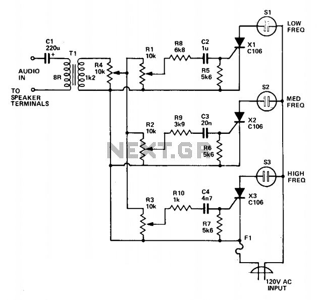
Three lights are controlled by three channels. One light pulses in response to the bass, another illuminates with mid-range sounds, and the last lights up for high notes. Four level controls allow adjustment of the overall light level and...
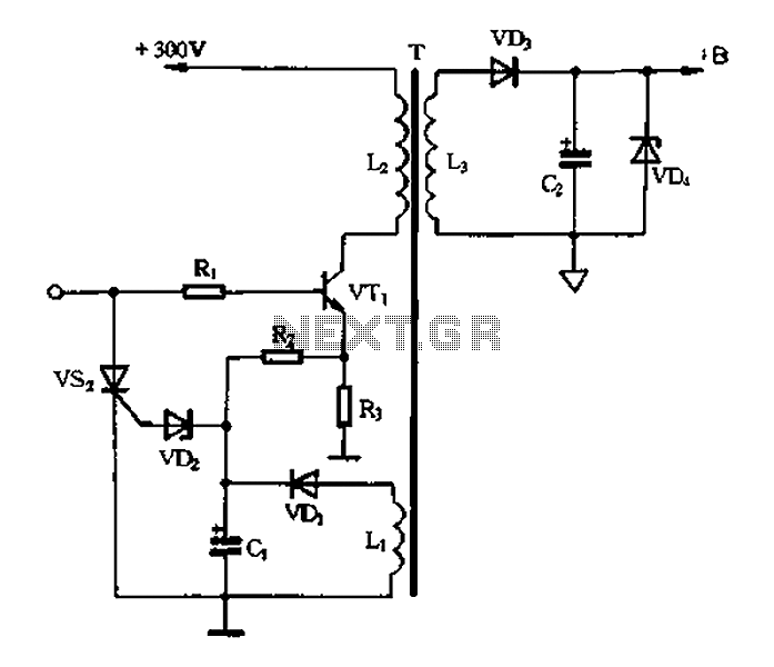
Color TV main power protection circuit The color TV main power protection circuit is designed to safeguard the television's power supply from various electrical anomalies, such as overvoltage, undervoltage, and short circuits. This circuit typically employs several components, including fuses,...
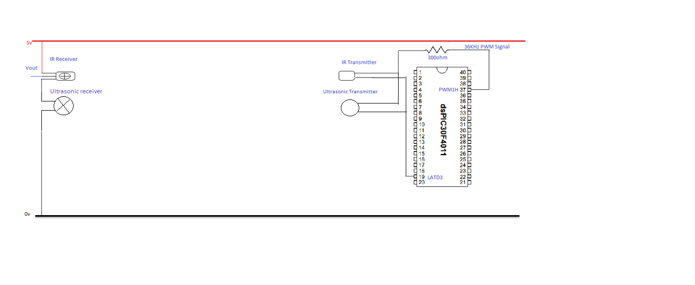
The objective of this experiment is to evaluate the range of the ultrasonic sensors (transmitter and receiver) utilized in this project. The sensor will be tested over a distance of 5 meters. The transmitter will be positioned directly facing...
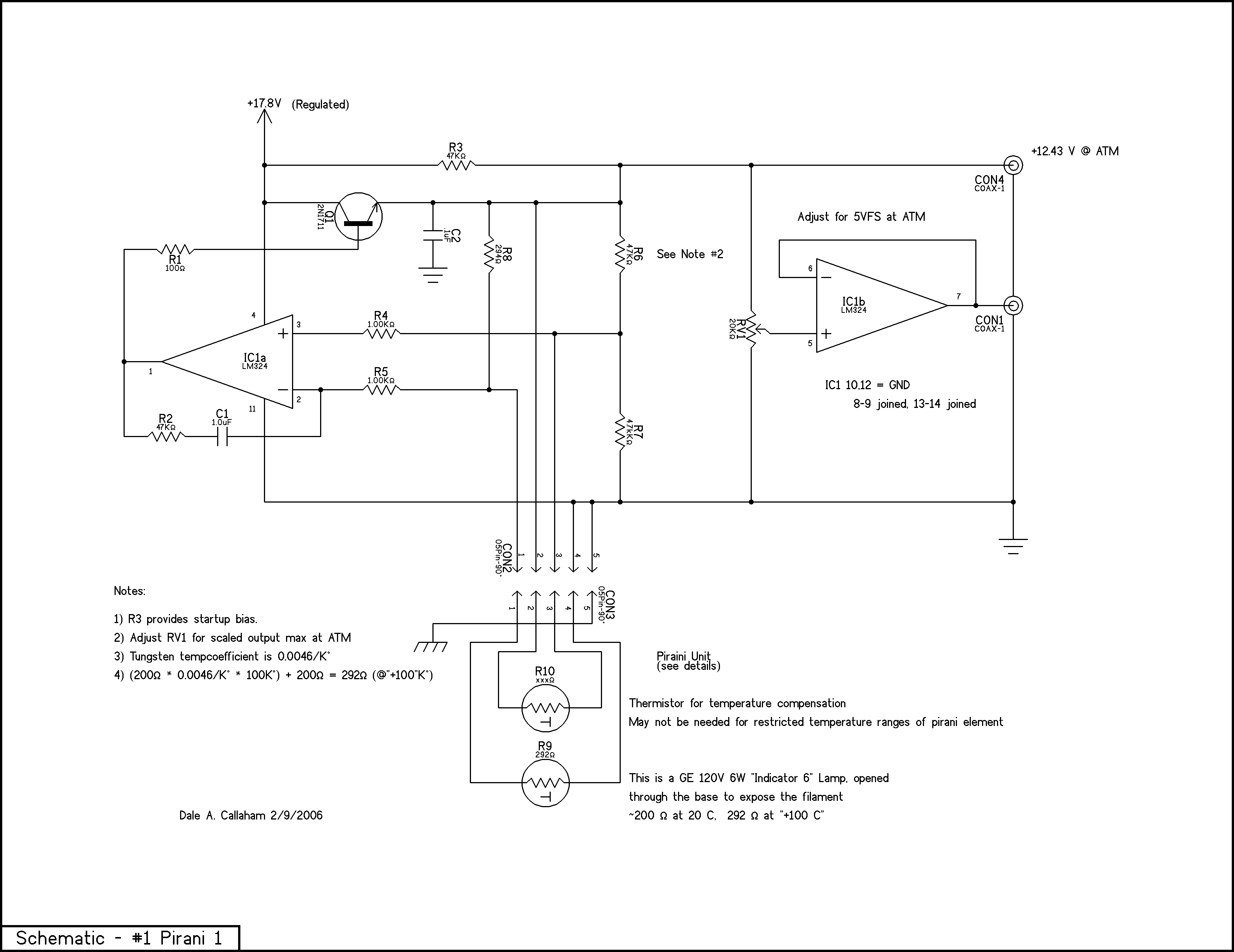
The principle is that the resistance of metals increases at higher temperatures, and a heated wire suspended in a gas will lose heat by conduction and convection in proportion to the number of gas molecules present; thus, the heat...
An electronic project to construct an LC meter project kit of exceptional accuracy to measure both inductance and capacitance—an inductance meter and capacitance meter all in one unit. It is readily available as a comparatively inexpensive kit, which is...
Both transistors should be low noise types. In the original circuit, BC650C was used, which is an ultra-low noise device. These transistors are now hard to find, but BC549C or BC109C are good replacements. The circuit is self-biasing and...