
colour organ
The Colour Organ is an electronic device designed to produce visual light displays that correspond to the sound frequencies of music. This project typically involves the use of a sound-sensitive circuit that detects audio signals and translates them into varying light patterns. The fundamental components of a Colour Organ circuit include a microphone or audio input, a frequency analyzer, and an array of light-emitting diodes (LEDs) or incandescent bulbs.
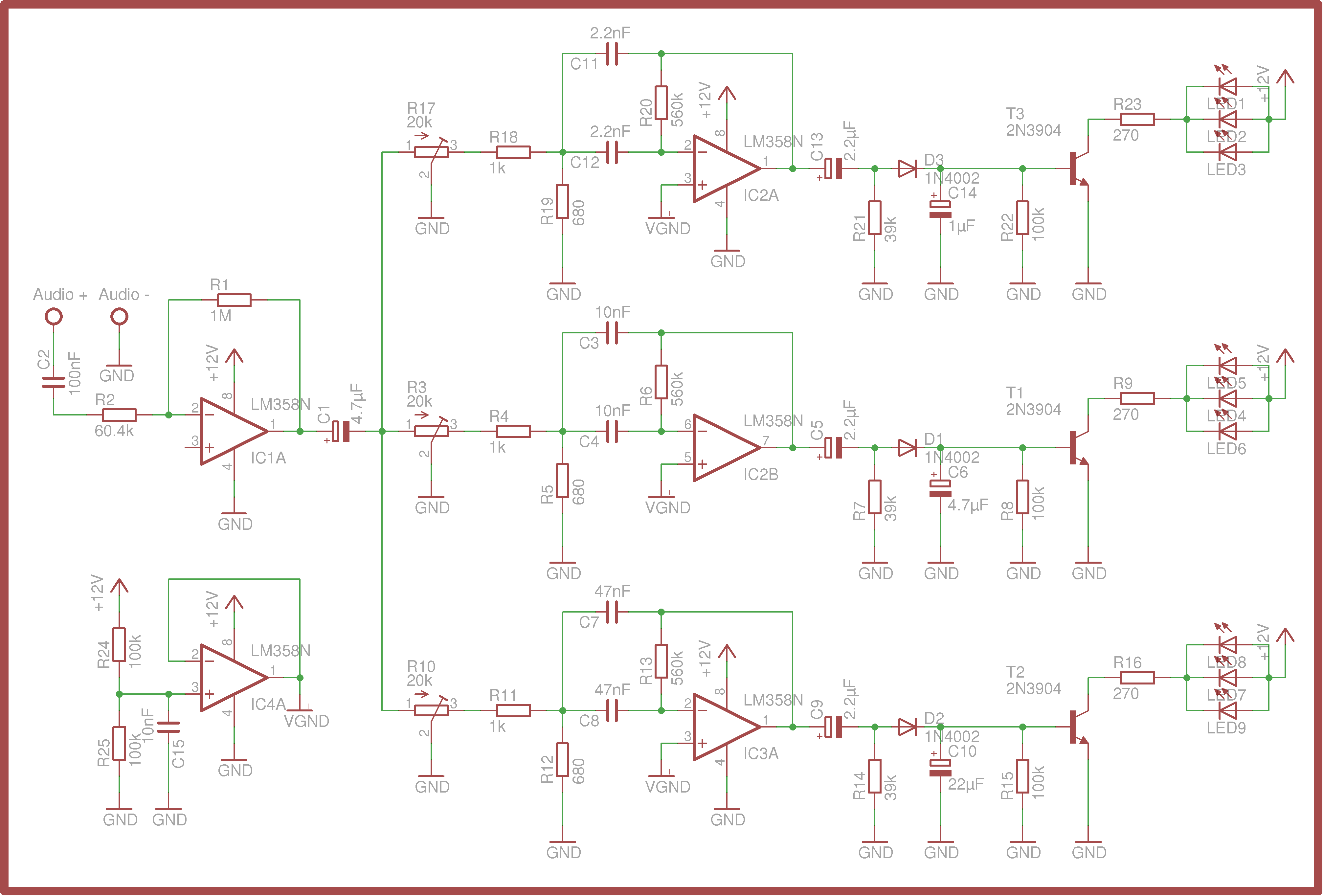
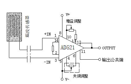
In constructing a Colour Organ, the circuit begins with an audio input stage where sound waves are captured. A microphone may be used to convert sound waves into an electrical signal, which is then filtered to isolate specific frequency ranges. The filtered signals are processed by a frequency analyzer, which divides the audio input into different frequency bands—commonly low, mid, and high frequencies. Each of these frequency bands is assigned to control a specific group of lights.
The output stage of the Colour Organ consists of driver circuits that control the brightness and on/off states of the lights based on the intensity of the signals from the frequency analyzer. This is typically achieved using transistors or relays that switch the lights on or off in response to the audio input. The result is a dynamic light show that enhances the auditory experience by visually representing the music being played.
The Colour Organ can be further enhanced with additional features such as adjustable sensitivity controls, multiple output channels for various light colors, and even programmable light patterns. This project not only serves as an engaging way to visualize sound but also provides valuable insights into the principles of audio processing and electronic circuit design.Colour Organ Videos Complete instructions this episode Weekend Projects can be found Fifteen years ago I bought a box from my uncle Here`s what it does.. 🔗 External reference
Related Circuits
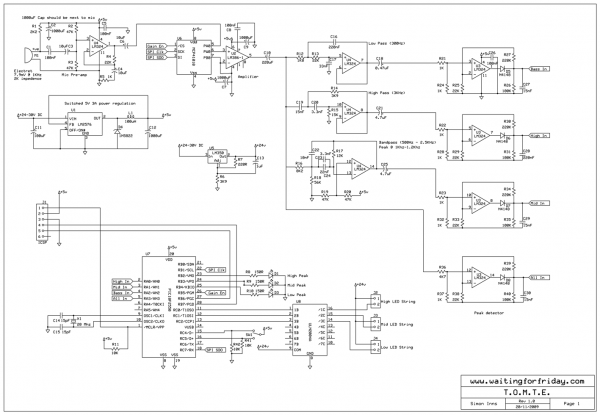
Most existing designs utilize direct switching of lights without any software control and include manual potentiometers for light sensitivity and overall gain settings. There are limited references regarding the frequency filter circuitry, explaining the specific frequencies the circuit is...

Flash-back to the 60's with this 5 channel unit with up to 100 watts per channel. This unit uses a PIC16F84 with an 8 bit A/D. The signal from both stereo channels is combined and digitized. Each of 5...
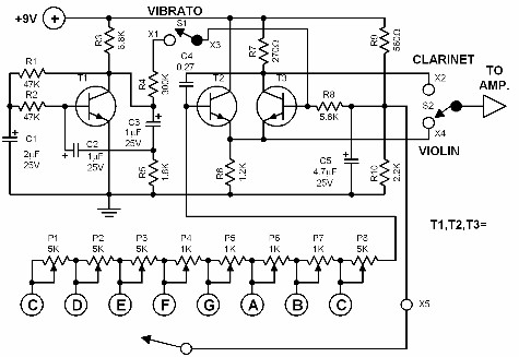
This electronic organ is simple to construct and can provide hours of enjoyment, particularly for children. The circuit is fundamentally an emitter-coupled oscillator consisting of transistors T2 and T3. A square wave voltage can be sampled from the collector...
This schematic illustrates a simple 555 organ circuit, which consists of two main components: the 555 timer circuit that generates tones and an LM386 amplifier for driving an 8-ohm speaker. The circuit produces slightly different tones when each switch,...
The component is deformed due to various thermal influences during processing, which compromises the original machining accuracy and introduces errors. In precision finishing, the effect of thermal deformation is particularly significant, leading to processing errors that can exceed 40%....
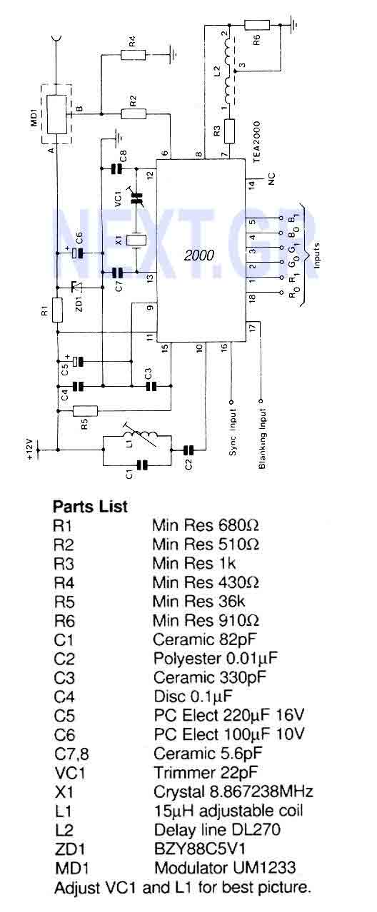
A PAL color encoder and video summer which requires just composite sync and composite blanking inputs, and a 6-bit binary coded input giving the color information. The inputs are organized as 2 bits per primary color with gamma correction...