
Color organ with PIC16F84

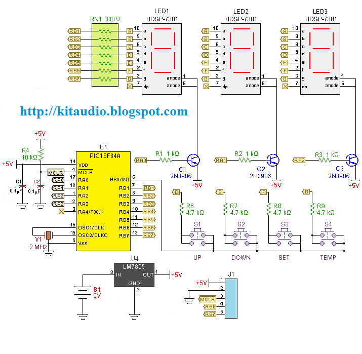
The described circuit is a five-channel audio processing unit capable of delivering up to 100 watts per channel. Central to its operation is the PIC16F84 microcontroller, which features an 8-bit analog-to-digital converter (A/D) for digitizing audio signals. The unit accepts stereo audio inputs, which are combined into a single signal before being processed.
The core of the audio processing involves a 16-point Fast Fourier Transform (FFT), which allows the input signal to be analyzed across five distinct frequency bands. This frequency analysis is essential for applications such as audio equalization or dynamic range control, where it is necessary to manipulate specific frequency ranges independently.
After the FFT processing, the output levels for each frequency band are converted to Pulse Width Modulation (PWM) signals. This method of signal modulation is efficient and effective for controlling the operation of solid-state relays, which are employed to switch power to the output channels. The use of PWM allows for precise control over the power delivered to each channel, enabling fine-tuning of the audio output.
The entire assembly is housed within a power distribution box, which not only provides necessary electrical outlets for powering the device but also offers ample space for the electronic components. This design choice emphasizes practicality while maintaining a retro aesthetic reminiscent of audio equipment from the 1960s.
The integration of both FFT processing and PWM control within a single microcontroller is a notable engineering achievement, demonstrating the capability of modern microcontrollers to handle complex signal processing tasks. The software architecture is designed to interleave these processes, ensuring that both FFT calculations and PWM signal generation can occur seamlessly without significant latency.
For those interested in replicating this design, additional resources such as the software listing and schematic diagrams are available for review. However, it is advised that individuals attempting to build this circuit have a solid understanding of microcontroller programming and electronic circuit design principles.Flash-back to the 60's with this 5 channel unit with up to 100 watts per channel. This unit uses a PIC16F84 with an 8 bit A/D. The signal from both stereo channels is combined and digitized. Each of 5 frequency bands is processed using a 16 point FFT. Then the level of each channel is output as PWM (pulse width modulation) to a set of solid state relays. The device is housed in a cheap power distribution box. This provides the 110 volt outlets along with plenty of room for the electronics. The big trick here was to perform the FFT and the PWM with a single processor. If you wish, check out the software listing, and see how the two processes are interleaved. As usual, you can also peruse the schematic allong with the Hex File. Also, as usual, you are on your own if you actually want to build one of these. 🔗 External reference
Related Circuits
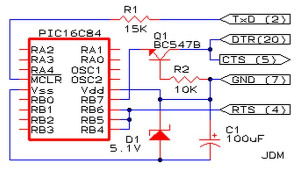
Affordable PIC Programmer. This programmer is compatible solely with the PIC16F84 microcontroller. It is reliable, as it rarely encounters errors, and functions well with nearly all computer systems, in contrast to some alternatives. The PIC programmer designed for the PIC16F84...
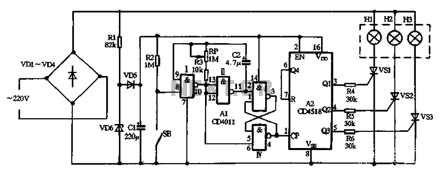
A colorful decorative lights loop circuit is depicted. It includes a power conversion circuit, a clock signal generator, and a color and lighting control circuit comprising several components. The circuit operates from a 220V AC source, which is rectified...
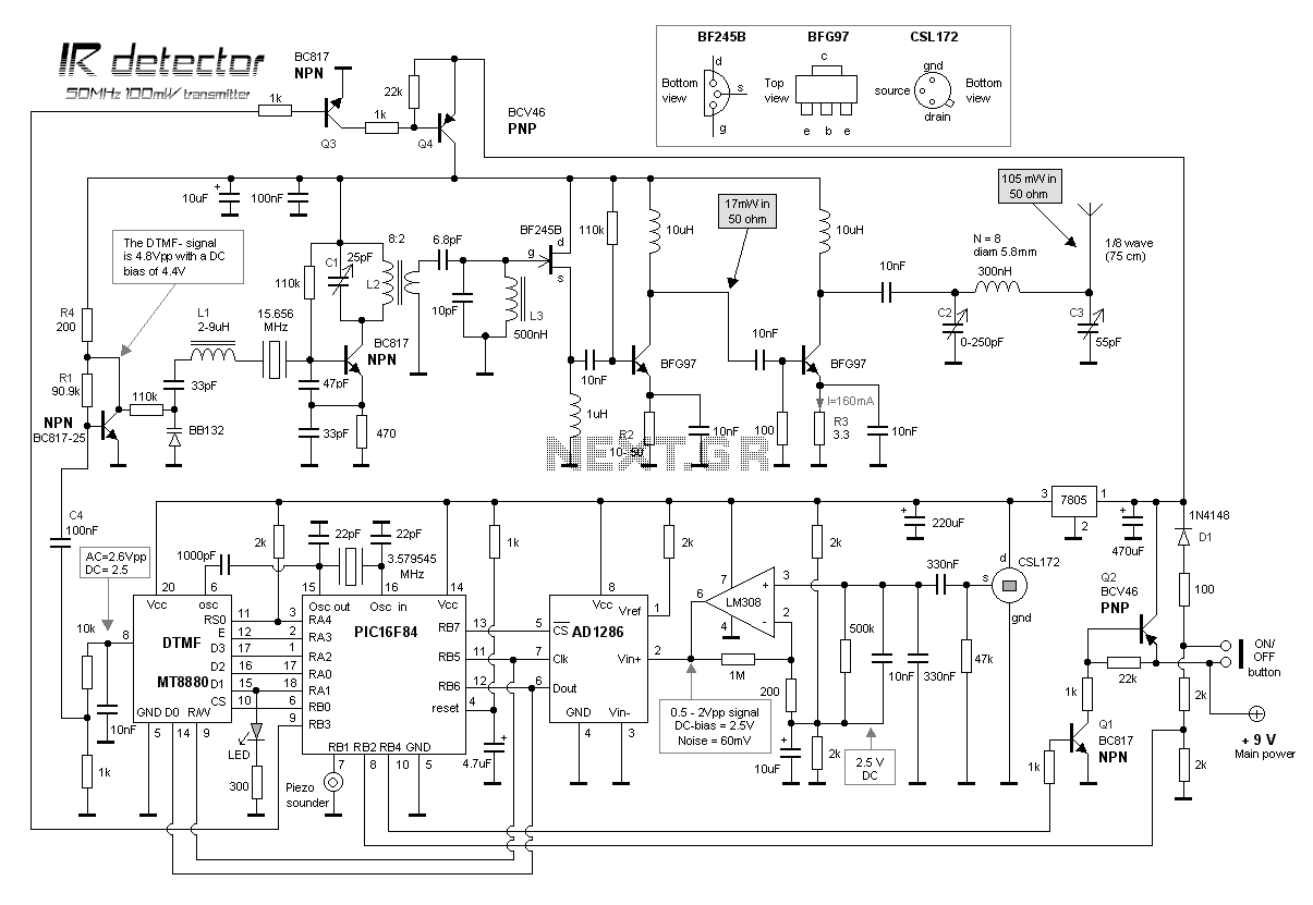
This project is about an IR-detector (Infra Red) combined with a 100mW 50MHz transmitter. The detector is sensitive to changes in IR-spectrum and is commonly used in burglar alarms. When the detector senses a person/animal/ghost/angry clown, it will transmit...
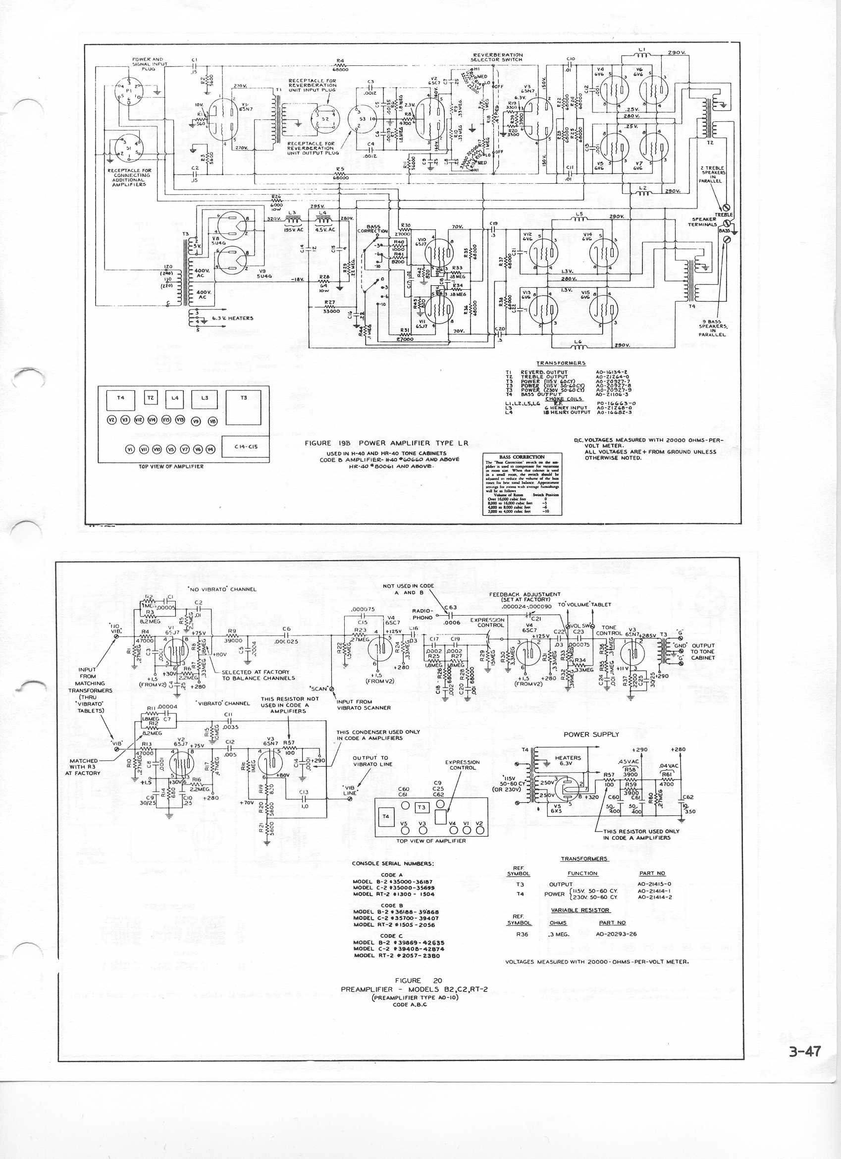
During a practice session on a Hammond C2 organ, the sound unexpectedly diminishes and becomes soft to the point of being inaudible. The Hammond C2 organ is an electromechanical instrument that utilizes a unique tonewheel generator system to produce sound....
Redesign a complex solution using minimal external components, resulting in a low-cost application that provides high-precision measurements. This digital thermometer microcontroller project utilizes a watchdog timer function to measure temperature. The watchdog timer (WDT) on all PIC microcontrollers has...

This project requires a 1200 RPM synchronous motor and a light source composed of a vertically arranged row of LEDs, positioned approximately 6 inches from the screw. The intention is to enclose all components within a clear plastic cabinet...