
555 organ circuit

The 555 organ circuit utilizes the 555 timer in astable mode to generate audio frequencies corresponding to piano notes. The frequency output is determined by the resistors R1 to R7, which are connected to the control pins of the 555 timer. Each switch (S1 to S7) is linked to a different resistor, allowing the user to select various tones by closing the switches. The LM386 amplifier is employed to amplify the audio signal produced by the 555 timer, ensuring adequate power is delivered to the 8-ohm speaker for clear sound output.
In addition, the circuit can be enhanced by incorporating more switches with variable resistors, which would enable the generation of additional tones. This flexibility is particularly useful for users seeking a wider range of musical notes. The variable resistor R9 serves as a master control, providing a means to adjust the pitch of all selected tones simultaneously, facilitating fine-tuning of the overall sound.
Powering the circuit with a DC supply of 9 to 12 volts ensures optimal performance of both the 555 timer and the LM386 amplifier. Proper decoupling capacitors should be included near the power supply pins of the ICs to minimize noise and ensure stable operation. Overall, this simple yet effective circuit design offers a straightforward approach to creating a compact electronic musical instrument.Here is a schematic of a simple 555 organ circuit. The circuit is consist of two parts first 555 circuit of organ and second lm386 amplifier for driving 8 ohms speaker. The circuit will generate slightly different tone by pressing each switch from S1 to S7 and work like a piano.
Use 100K small variable resistors for R1 to R7. The frequency of tone can be changed by adjusting the variable resistors R1 to R7, adjust them like piano tone 1, 2, 3, 4, 5. , and then change these variable resistors to fix resistors if required. More switches with variable resistors can be added before S1 for more tones. You can also change tone of all switch from S1 to S7 at once by adjusting the variable resistor R9. Apply 9 to 12 volt DC to power the circuit. 🔗 External reference
Related Circuits
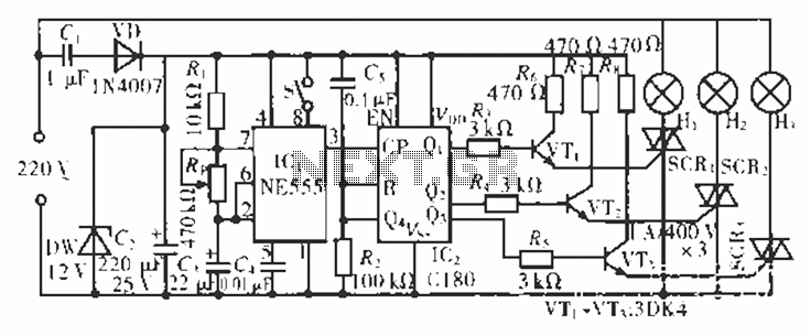
The circuit operates at 220 V AC using a C1 buck converter and a DW regulator. The VD ensures the entire stream is processed, and C2 provides a filtered output of 12 V DC for the voltage supply control...
This circuit design is intended for conducting harmless experiments with high-voltage pulses, functioning similarly to an electrified fence generator. The pulse repetition frequency (PRF) is determined by the time constant of the resistor-capacitor network R1-C3 in the feedback loop...
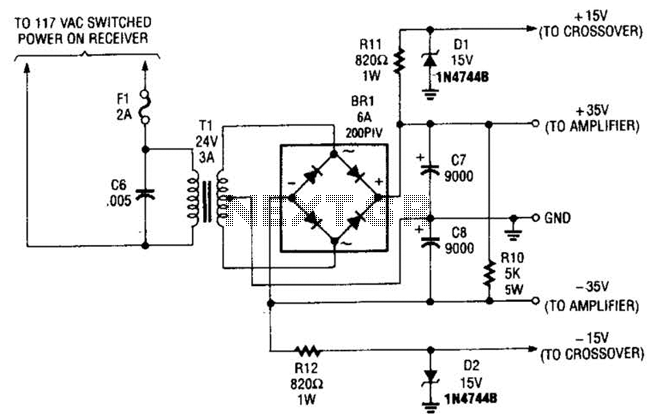
This power supply is designed to power a 100-W low-frequency amplifier and is capable of supporting various mono or stereo amplifiers within the medium power range, specifically those that require 30 to 35 V. The power supply circuit is engineered...
A schematic of a flip-flop LED flashing circuit is presented. This circuit functions as an astable multivibrator that activates LEDs sequentially upon power application. It is compatible with voltage inputs ranging from 6 to 12 volts, and can also...

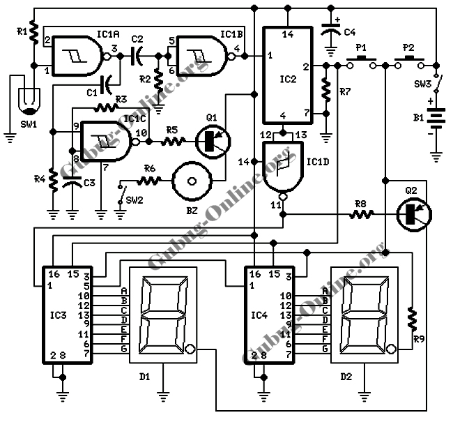
All of ACC's repeater and remote base products support the control of synthesized remote base transceivers. One form of frequency control supported is compatible with transceivers using thumbwheel frequency selection. The controllers supply BCD (binary coded decimal) formatted data...
This two-transistor AM radio circuit is also referred to as a "mini-radio." It utilizes only two transistors and a few passive components, which makes it very easy to construct. The two-transistor AM radio circuit operates by utilizing a simple design...