
Colpitts Oscillator Practical Project

The Colpitts oscillator is a type of LC oscillator that utilizes a combination of inductance (L) and capacitance (C) to generate oscillations. The circuit typically consists of a transistor amplifier, an inductor (L1), and two capacitors (C2 and C3) that form a voltage divider. The feedback network, composed of C2 and C3, is crucial in determining the frequency of oscillation, which is calculated using the formula:
\[ f = \frac{1}{2\pi \sqrt{L \cdot C_{total}}} \]
where \( C_{total} \) is the equivalent capacitance of C2 and C3 in series. The oscillator's frequency can be adjusted by changing these component values.
In operation, the transistor amplifies the oscillations generated by the LC tank circuit, and the output can be observed on an oscilloscope. The design allows for experimentation with R3 to fine-tune the gain of the amplifier, which directly influences the amplitude of the output signal. It is essential to ensure that the circuit is powered within the specified voltage range to prevent damage to the components.
The breadboard setup is ideal for initial testing, allowing for easy modifications of component values and configurations. Observations during testing should focus on the waveform shape, amplitude stability, and the overall performance of the oscillator. The ability to achieve a peak-to-peak output voltage greater than the supply voltage is a noteworthy aspect, emphasizing the efficiency of energy transfer in the resonant circuit. This phenomenon highlights the importance of resonance in LC circuits, as it maximizes the energy exchange between the inductor and capacitors, resulting in higher output voltages.
When transitioning to a stripboard layout, care must be taken to maintain the integrity of the circuit connections and component placements to ensure consistent performance. The final circuit can be optimized based on empirical results gathered during the testing phase on the breadboard.Build the Colpitts oscillator shown using either breadboard (proto board) or strip board, then test the oscillator`s operation using a multi meter and oscilloscope. This Colpitts oscillator produces a sine wave output in excess of 12Vpp at an approximate frequency set by the values chosen for L1, C2 and C3.
It will operate from a 9V battery, or a DC power supply up to 12V. Supply current at 9V is around 20mA. The circuit can be built on breadboard for testing purposes, where it will be found that the value of R3 is fairly critical. This 68 ohm resistor could be replaced by a slightly higher or lower value to alter the amplifier gain for experimentation.
The values given for the circuit should work reliably when built on strip-board. Construct the circuit on breadboard and experiment with different component values. The values shown on the circuit schematic above should give reliable oscillation. Note how some values produce different amplitudes or better wave shapes. It should be possible to obtain a good sine wave with a peak to peak output amplitude even greater than the supply voltage. This is a particular feature of LC oscillators as the AC output voltage depends on the amount of current circulating around the tuned circuit at resonance.
But remember that a larger output voltage will also mean a higher collector current. 🔗 External reference
Related Circuits
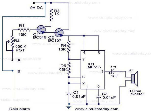
The operation of the rain alarm circuit is explained in detail. The rain alarm project is outlined along with a circuit diagram. The rain alarm circuit is designed to detect the presence of rain and alert users through an audible...
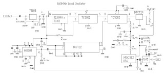
This 860 MHz Phase Locked Loop (PLL) oscillator circuit is designed for a 1200 MHz transverter's local oscillator with 435 MHz rigs. The oscillator utilizes Toshiba PLL synthesizer integrated circuits (ICs). The TC9122P serves as a preset counter for...
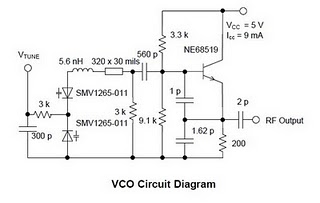
The high performance of modern set-top DBS TV tuners necessitates the development of broadband voltage control oscillator (VCO) designs that are cost-effective. Design engineers face the challenge of creating high-performance, low-cost VCOs. The traditional Colpitts oscillator design is commonly...
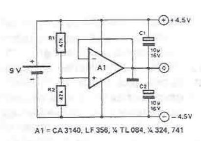
A symmetrical power supply can be designed using this circuit diagram. This symmetrical power supply is constructed with a simple operational amplifier and some classic electronic components. Resistors R1 and R2 form a high impedance voltage divider. The operational...
The figure illustrates the FM modulation circuit of a crystal oscillator. FM modulation can be achieved through direct and indirect methods. The direct FM method involves directly altering the frequency of the oscillating circuit. While this approach is straightforward,...
The 8051 microcontroller can play music tones. Here is a sample circuit and code that will play the music for "wishes you to be..." The 8051 microcontroller is a versatile and widely used microcontroller in embedded systems, capable of performing...