
Rain Alarm Circuit-Science project with rain detector circuit-Working

The rain alarm circuit is designed to detect the presence of rain and alert users through an audible or visual signal. The fundamental components of this circuit typically include a rain sensor, a microcontroller or comparator, a power supply, and an output mechanism such as a buzzer or LED.
The rain sensor is the primary element that detects moisture. It usually consists of two conductive plates that, when wet, allow current to flow between them. This change in conductivity can be monitored by the microcontroller or comparator, which processes the signal to determine whether rain is present.
When the sensor detects moisture, the microcontroller activates the output mechanism. This could be a buzzer that emits sound to alert the user or an LED that lights up to provide a visual indication of rain. The circuit may also include additional features such as adjustable sensitivity settings or a delay timer to prevent false alarms from brief rain showers.
Power supply considerations are crucial for the circuit's operation. A battery or a regulated power source is typically used to ensure that the circuit operates reliably under varying environmental conditions.
A schematic diagram of the rain alarm circuit will illustrate the connections between these components, showcasing how the sensor interfaces with the microcontroller and the output devices. Proper layout and component selection are essential for ensuring optimal performance and longevity of the circuit.The rain alarm circuit working is explained in detail. The rain alarm project is explained with circuit diagram.. 🔗 External reference
Related Circuits
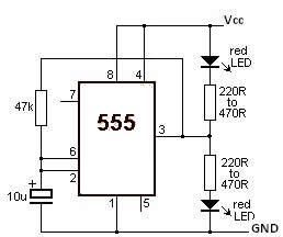
This LED flasher circuit utilizes the 555 timer integrated circuit (IC). The circuit diagram is straightforward and requires only a few external components. When operational, the red LEDs will flash sequentially at a predetermined frequency, similar to the indicators...
The frequency is controlled by pin 5 of the integrated circuit (IC). When the power supply is activated, the capacitor charges gradually, which alters the voltage at pin 5 of the IC, causing the frequency to increase incrementally. Once...
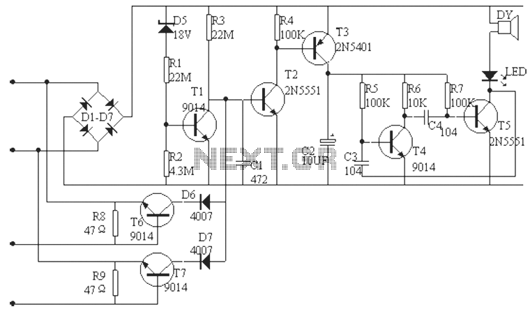
The phone alarm device is designed to monitor and prevent unauthorized use of a telephone line. When interference signals are detected on the line due to theft attempts, the alarm activates, preventing the thief from making calls while alerting...

This easy-to-construct "Handy Pen Torch" electronic circuit has a low component count and utilizes two power white LEDs for lighting. It operates on a low voltage supply of 4.8V DC. The Handy Pen Torch circuit is designed to provide a...

This circuit utilizes a 556 timer IC to initially generate a low-frequency square wave, which is then modulated to produce two alternating tones of approximately 400 Hz and 500 Hz. The circuit is designed to create a warble alarm...
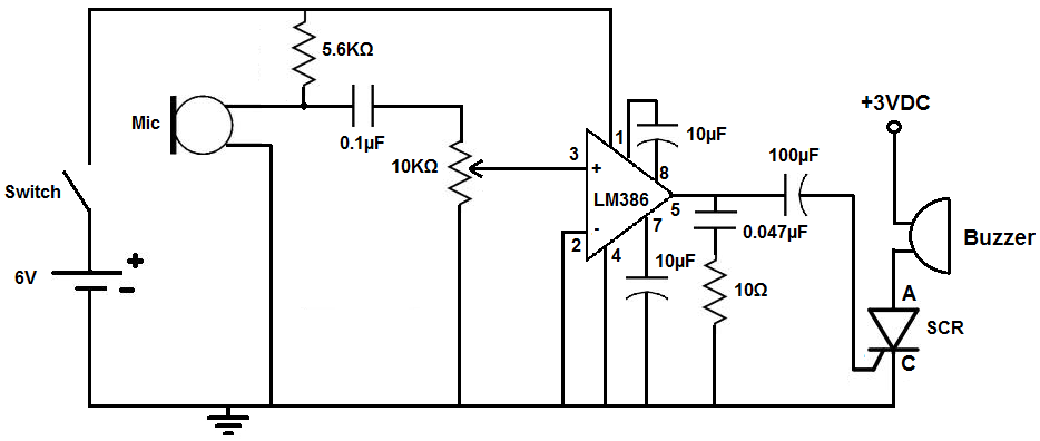
This circuit is designed to activate an alarm when it detects sound above a specified threshold. The alarm serves as a notification for any sound in areas that are typically quiet, such as quiet zones. Under normal quiet conditions,...