
Combination Lock Circuit
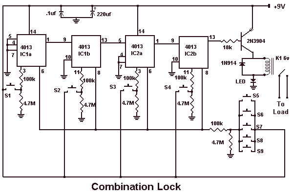
The described circuit functions as a sequential lock mechanism, utilizing a series of momentary push-button switches (S1, S2, S3, S4) to control a load (K1). The operational principle is based on the requirement to press the switches in a specific order to activate the lock.
The circuit can be constructed using a microcontroller or a simple logic circuit with flip-flops to track the correct sequence of inputs. Each momentary switch is connected to an input pin of the microcontroller or to the clock input of a flip-flop. When a switch is pressed, it sends a signal to the circuit, which checks if the input corresponds to the next expected switch in the sequence.
If the correct switch is pressed, the circuit proceeds to the next switch in the sequence. If an incorrect switch is pressed, the circuit resets, requiring the user to start over. This feature can be implemented using a reset mechanism, which can be a simple logic gate configuration or a software routine in a microcontroller.
The wiring of the switches can be arranged in various configurations, allowing for flexibility in the choice of switch combinations. For instance, the switches can be connected in parallel to a common input line, with each switch having a unique identifier in the software or logic circuit.
The load (K1), which could be a solenoid, relay, or any other actuating device, is activated once the complete sequence is successfully entered. To ensure user feedback, the circuit may incorporate LEDs or buzzers to indicate the status of the input sequence, providing visual or auditory cues for correct or incorrect inputs.
Overall, this circuit is a straightforward yet effective implementation of a sequential locking mechanism, suitable for various applications requiring controlled access.This circuit is very basic to build. To open a the lock which is connected to the K1 Load you must press each momentary switch in the correct sequence. The sequence used in this circuit is S1,S2,S3,S4. If any of the other switches are pressed the circuit will reset and you will need to start over. Depending on how you wire the switches, you can use any 4 switch combination. 🔗 External reference
Related Circuits
This microphone preamplifier utilizes the low-noise integrated circuit uA739. The circuit serves as an example of an effective preamplifier design for dynamic microphones. The integrated circuit contains two identical preamplifier circuits, with the second preamp functioning in the same...
The relay control allows for multiple pairs of contacts to be connected in parallel, enabling the circuit to handle a large lamp power. The design is straightforward; by simply changing the capacitance of the capacitor, different flash frequencies can...

This circuit is for an audio equalizer that is commonly found in commercial products such as high-fidelity systems, car audio, and stage equipment; however, published circuits for these devices are quite rare. This design features equalizer bands. The circuit...
A highly beneficial project involving a crystal tester circuit, also known as an xtal tester circuit, constructed with only a few components. The circuit forms an oscillator that will only oscillate if the crystal under test is functioning properly....
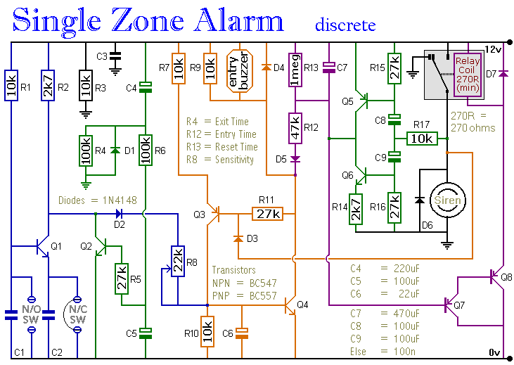
The circuit includes automatic exit and entry delays, a timed bell cut-off, and a system reset feature. It accommodates both normally-open and normally-closed switches, making it compatible with standard input devices such as pressure mats, magnetic reed contacts, foil...
A circuit designed to multiply the width of incoming pulses by a factor that can be greater or less than unity is straightforward to construct. It features a single adjustable potentiometer for selecting the multiplying factor. This factor is...