
Alternately flashing one of a plurality of sets of high-power lights a chain circuit
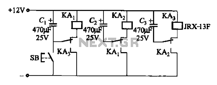
The described circuit utilizes a relay to control high-power lamps efficiently. The relay acts as a switch that can handle significant current loads, allowing for the operation of large lamps without the need for complex control systems. Each relay can be connected to multiple contacts in parallel, which increases the overall current capacity of the circuit. This feature is particularly useful in applications where high-intensity lighting is required.
The circuit's simplicity lies in its design, where the primary variable component is the capacitor. By adjusting the capacitance value, the timing characteristics of the circuit can be modified. This results in different flash frequencies, which can be tailored to suit specific lighting effects or operational requirements.
In practical terms, the relay is typically activated by a control signal, which could be a manual switch or an automated control system. Once energized, the relay closes its contacts, allowing current to flow to the lamp. The capacitor in the circuit charges and discharges, controlling the timing of the relay's operation and thus the frequency of the lamp's flashing.
To implement this circuit effectively, key parameters such as the relay's contact ratings, the voltage and current specifications of the lamp, and the desired flash frequency should be carefully considered. Additionally, the capacitor's voltage rating must exceed the maximum voltage in the circuit to ensure reliable operation and prevent failure.
Overall, this relay-controlled lamp circuit offers a versatile and efficient solution for applications requiring variable flash rates and high power handling capabilities.As a result of the relay control (several pairs of contacts, if more capacity is connected in parallel), so the lamp power can be large, the circuit is very simple, just change the capacitor capacitance, you can get a different flash frequency.
Related Circuits
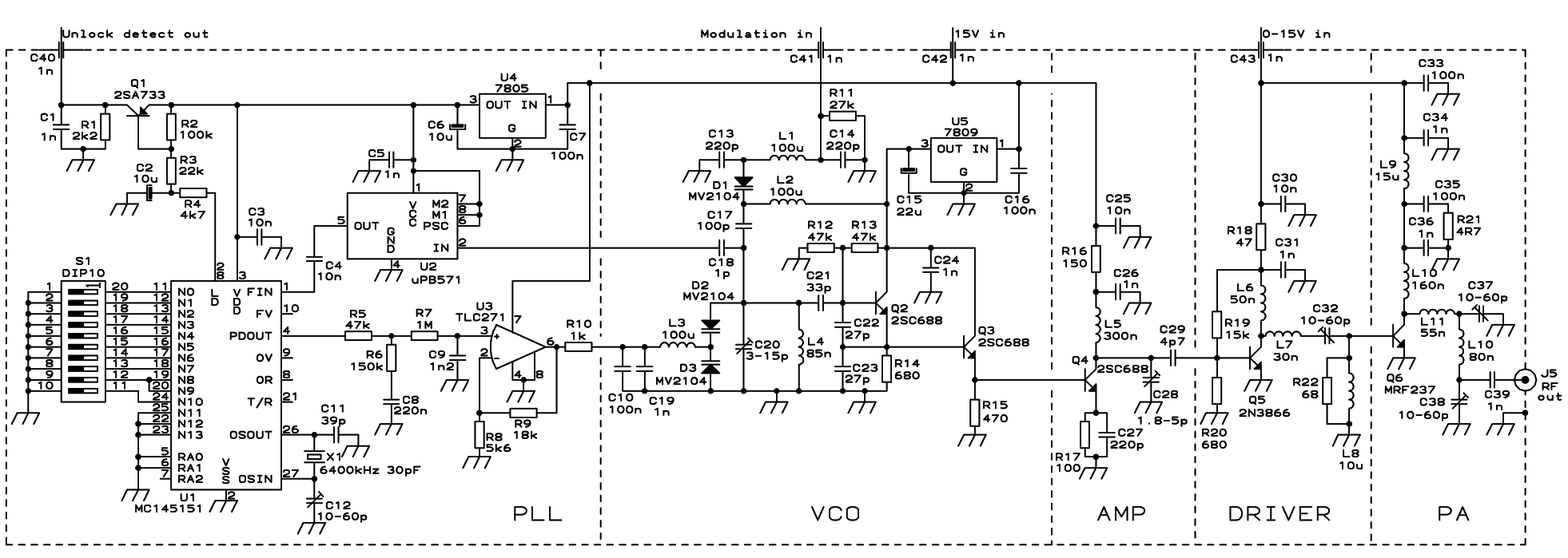
The PLL transmitter exciter is designed to provide a stable, low noise, frequency-selectable RF signal, which is amplified to a controllable output power sufficient to drive a power amplifier. It utilizes a PLL frequency synthesizer based on the MC145151,...
A transistor optocoupler interface circuit, as described in section 15.1.6, has been implemented. This circuit serves as a transistor interface with other circuits. The transistor optocoupler interface circuit utilizes a light-emitting diode (LED) and a phototransistor to achieve electrical isolation...

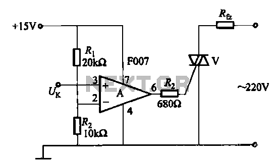
This is a simple electronic circuit for a clap switch project. It is suitable for beginner electronics learners who enjoy experimenting with new projects. The circuit can turn on or off a 220V electronic device, such as a fan...

The circuit utilizes the HL-169B voice alarm integrated circuit (IC). It is designed for use in security applications, including glass doors, car doors, and windows, to act as a burglar alarm. When a thief applies force to these items,...
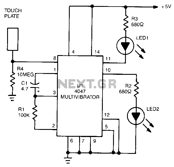
The 4047 is configured as a monostable multivibrator circuit, also known as a one-shot, which is triggered by a negative transition of the signal applied to its pin 6 input. The duration of the multivibrator's output pulse is determined...
The buba oscillator initially failed to oscillate. The first step is to check the fundamental components, as minor errors in the values of capacitors, resistors, and inductors can significantly impact performance. It is advisable to measure component values with...