
Combination Lock With Auto Reset
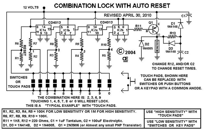
The combination lock circuit employs a 4-digit input mechanism, which can be implemented using a keypad or a series of momentary push buttons. Each button corresponds to a digit from 0 to 9, allowing the user to input their desired combination. The circuit is designed using CMOS technology, which contributes to its low power consumption, making it suitable for battery-operated applications.
Upon entering the correct combination, the circuit activates a relay or a transistor switch, which can control a locking mechanism or an alarm system. The auto-reset feature ensures that if the incorrect combination is entered, the system will automatically reset after a specified period, preventing unauthorized access attempts.
The power supply for the circuit can range from 9 to 15 volts, providing flexibility for various applications. A voltage regulator may be included to ensure stable operation within this range. Additionally, the circuit can incorporate indicators, such as LEDs, to provide visual feedback during the input process or to signal successful entry of the correct combination.
Overall, this combination lock circuit is an efficient and reliable solution for securing access to sensitive areas or devices, leveraging the advantages of CMOS technology for enhanced performance and energy efficiency.This circuit function for combination lock with auto reset. 4 Digit Enter Combination, C-Mos Design, Low Standby Power, and 9 to 15 Volt Operation .. 🔗 External reference
Related Circuits
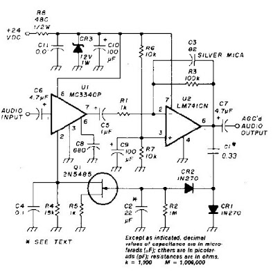
An audio signal applied to VI is passed through the operational amplifier 741, U2. After being amplified, the output signal V2 is sampled and applied to a negative voltage doubler/rectifier circuit composed of diodes CR1 and CR2, along with...
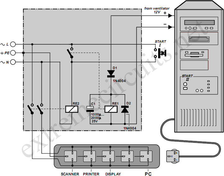
Downloading and CD-burning programs often offer the option to automatically shut down the PC upon completion of their tasks. However, this energy-saving feature is ineffective if all peripheral equipment remains connected to the mains and continues to consume power...
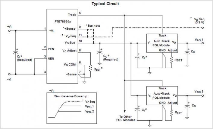
PTB78560BAS is a subpackage of PTB78560B. For a detailed description, please refer to PTB78560B. The datasheet for PTB78560BAS can be downloaded below. Provided by Texas Instruments. The PTB78560BAS is a specific variant within the PTB78560B family of components, designed for...
As a followup to my VCR Pong project, here is a gadget that is actually useful in the Real World! It superimposes the time of day, in "HH MM SS" format, in the bottom right-hand corner of an existing...
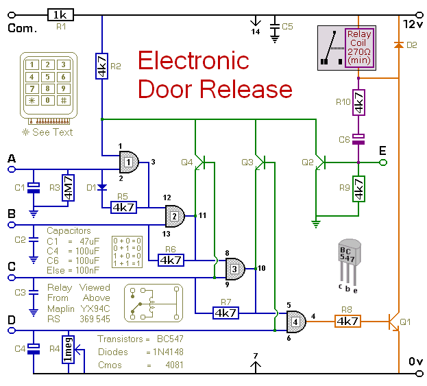
This circuit is designed to operate an electrical door-release mechanism, but it can also be used for other applications. Users can enter a four-digit code of their choice, which will energize a relay for a duration determined by the...
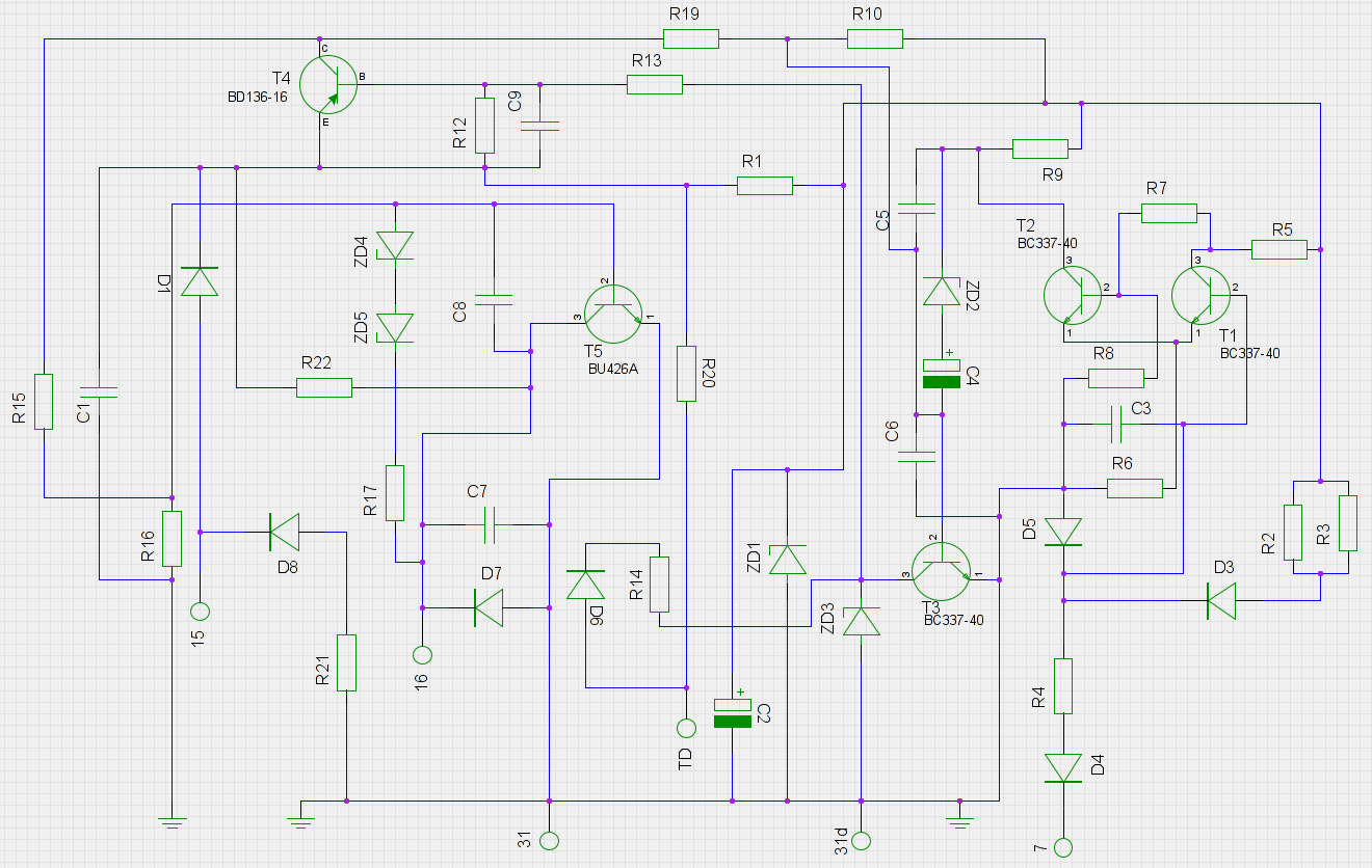
An old ignition module from a 1978 W116 model Mercedes-Benz is being reverse-engineered. The original circuit diagram is not available, so a new one has been created based on the printed circuit board (PCB). The circuit has been assessed...