
How To Build A Keypad-Operated Door-Lock Release

This electronic circuit schematic facilitates the operation of an electrical door-release mechanism, primarily allowing for controlled access through a keypad interface. The core functionality relies on a four-digit code input, which is processed by a relay mechanism. The system is designed to operate with a low standby current, making it suitable for battery operation, thereby enhancing its versatility in various applications.
The circuit is powered by a voltage supply ranging from 5 to 15 volts, with a typical configuration at 12 volts. The choice of relay is critical; it must be compatible with the supply voltage and should not be used for switching mains voltage directly due to the design limitations regarding isolation between high and low voltage components. For applications requiring mains voltage switching, a separate, appropriately rated relay should be installed away from the main board to ensure safety.
The keypad interface is constructed with four designated keys (A, B, C, D) for code entry, with additional keys connected to a common terminal. The logic of the circuit is designed such that pressing the correct sequence of keys energizes the relay, allowing for the release mechanism to be activated. The timing of the relay activation can be adjusted by modifying the values of components C4 and R4; a longer delay can be achieved with higher resistance settings, while immediate deactivation can be configured with a fixed resistor and capacitor.
In the event of incorrect key presses or out-of-sequence entries, the circuit incorporates fail-safes through the use of transistors Q2, Q3, and Q4 to ensure that erroneous inputs do not trigger the relay. This design not only enhances security but also provides a user-friendly interface, allowing for easy re-entry of the code after a mistake.
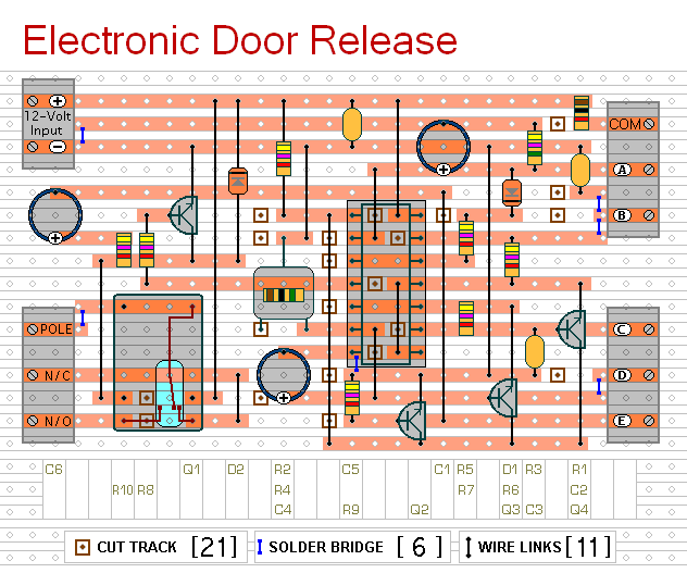
Overall, this circuit schematic is a robust solution for controlled access systems, providing flexibility in design and application while ensuring safety and reliability in operation. The accompanying support materials further assist users in building and implementing the circuit effectively.This circuit is designed to operate an electrical door-release mechanism - but it will have other applications. Enter the four-digit code of your choice - and the relay will energize for the period of time set by C4 & R4.
Use the relay contacts to power the release mechanism. The standby current is virtually zero - so battery power is a realistic option. The circuit is drawn with a 12-volt supply - but it will work at anything from 5 to 15-volts. All you have to do is choose a relay suitable for the supply voltage you want to use. Replace the SPCO/SPDT relay with a multi-pole relay - if it suits your application. Do not use the "on-board" relay to switch mains voltage. The board`s layout does not offer sufficient isolation between the relay contacts and the low-voltage components. If you want to switch mains voltage - mount a suitably rated relay somewhere safe - Away From The Board.
Choose the four keys you want to use as your code - and connect them to "A B C & D". Wire the common to R1 and all the remaining keys to "E". When you press your four keys - in the right order - the relay will energize. With the values of C4 & R4 as shown - and with R4 set to its maximum - the relay will de-energized about one minute after "D" is released. However - if you replace C4 with a 100nF capacitor - and replace R4 with a 4k7 fixed resistor - the relay will de-energize the moment "D" is released.
Any keys not wired to "A B C & D" are connected to the base of Q2. Whenever one of these "Wrong" keys is pressed - Q2 takes pin 1 low and the code entry fails. Similarly, if "C" or "D" is pressed out of sequence - Q4 or Q3 will take pin 1 low and the code entry will fail. If you make a mistake while entering the code - simply start again. The Keypad must be the kind with a common terminal and a separate connection for each key. On a 12-key pad, look for 13 terminals. The matrix type with 7 or 8 terminals will NOT do. A 12-key pad has eight "Wrong" keys connected to "E". If you need a more secure code - use a bigger keypad with more "Wrong" keys. The Support Material for this circuit includes a step-by-step guide to the construction of the circuit board, a parts list, a detailed circuit description and more.
🔗 External reference
Related Circuits
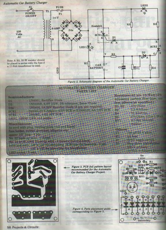
This project is designed for individuals interested in constructing their own Automatic Battery Charger. It has been developed by duc_tech. The Automatic Battery Charger project involves creating a circuit that can efficiently charge batteries without requiring constant supervision. The design...
Half of RL1 and RL2 manage the switching mechanism, while the other half connects to an application. The relays operate at 200 ohms above ground, with one terminal referenced to positive voltage, which deactivates them. RL1, when off, applies...
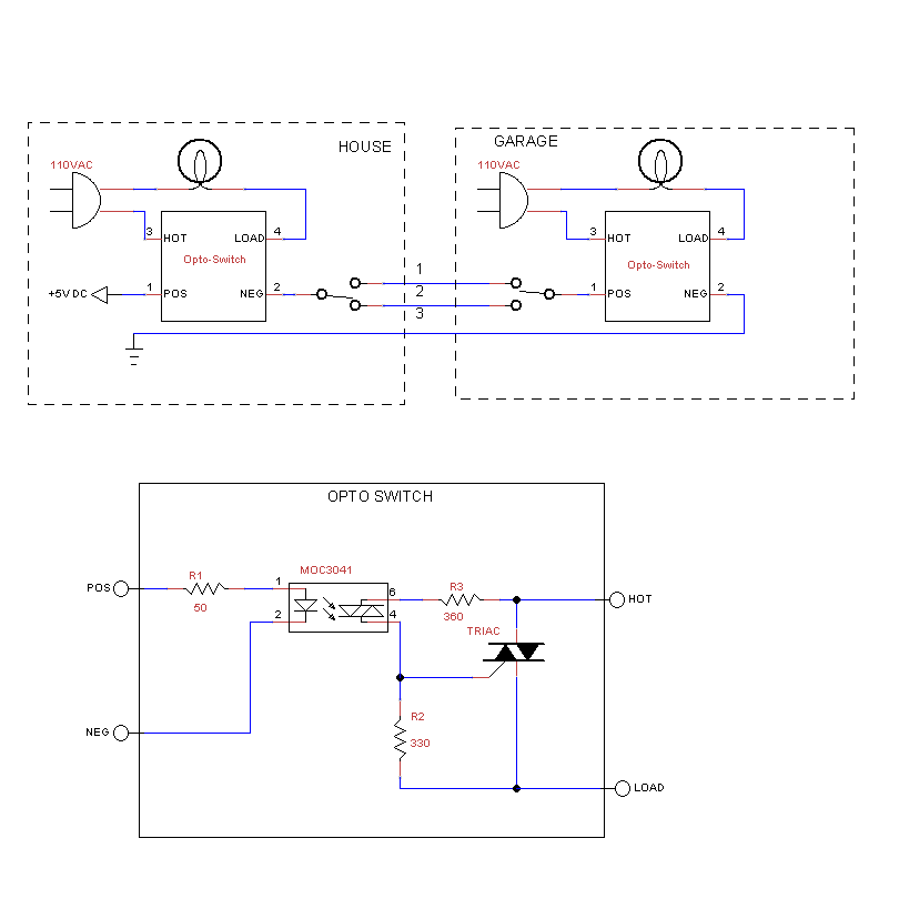
The rewiring of an entire house is underway following a significant malfunction of two antique knob and tube circuits. A challenge has arisen with the outdoor lighting setup, specifically concerning a detached garage that features a porch light above...
A newcomer has entered the field after completing several repairs and minor upgrades on tube amplifiers, including re-capping and addressing bias issues. The process of repairing and upgrading tube amplifiers involves several critical steps to ensure optimal performance and reliability....
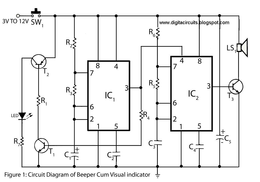
This circuit of a beeper and visual indicator is constructed using two timer integrated circuits (ICs) configured in an astable multivibrator mode. The frequency produced by IC1 is regulated by capacitor C1. The output from pin 3 of IC1...
This circuit is designed to operate an electrical door-release mechanism, but it can be adapted for other applications. Upon entering a four-digit code of the user's choice, the relay will energize for a preset duration. The relay contacts can...