
Two Simple Crystal Test Circuits
The first circuit utilizes a BC548 transistor in a Colpitts oscillator configuration, which is a type of LC oscillator that generates sinusoidal outputs. The oscillator's frequency is primarily determined by the values of the capacitors and the inductor in the circuit, with the crystal acting as a frequency-selective element. The insertion of a crystal allows for precise frequency control, as it introduces a high Q factor into the circuit, leading to stable oscillations. The output from the collector is then processed by the OA91 germanium diode, which rectifies the AC signal into a DC signal. This rectification is crucial for measuring the output oscillation amplitude, which is displayed on a connected meter. The amplitude of the oscillation, indicated by the meter deflection, is directly related to the activity of the crystal; a more active crystal will produce a larger deflection, indicating stronger oscillations.
In the second circuit, another BC548 transistor operates in conjunction with a crystal to form a similar Colpitts oscillator. However, this circuit takes its output from the emitter rather than the collector. This design choice allows for a different output characteristic and is advantageous in certain applications. The output is full-wave rectified, which means that both halves of the AC waveform are utilized, resulting in a more consistent DC output. The small DC bias generated from this rectification process is sufficient to turn on the second BC548 transistor, which is connected to an LED. This LED serves as a visual indicator of the oscillator's activity, lighting up in response to the oscillations produced by the circuit. The interaction between the crystal and the transistors in both circuits exemplifies the principles of oscillation and signal processing in electronic design.In the first circuit, above the BC548 is wired as a colpitts oscillator, the frequency tuned by insertion of a crystal. A good crystal will create high frequency oscillations, the output at the collector is rectified by the germanium OA91 diode and a deflection will appear on the meter.
Thw more active the crystal, the higher the output deflection which may be adjusted with the preset. The next circuit uses a working crystal again used to control the frequency of a colpitts oscillator. This time the output from the oscillator is taken from the emitter and is full wave rectified, the small dc bias will then directly cause the second BC548 to light the LED.
🔗 External reference
Related Circuits
A continuity tester is useful for verifying that there is a conductive path between two points. This circuit offers the advantage of being highly sensitive, providing both visual and audible indications of continuity. An audible tester is particularly beneficial...
This simple circuit utilizes a 741 operational amplifier (op-amp) in differential mode as a continuity tester. The voltage difference between the non-inverting and inverting inputs is amplified by the op-amp's full open-loop gain. Initially, the 470kΩ and 10kΩ resistors...
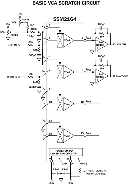
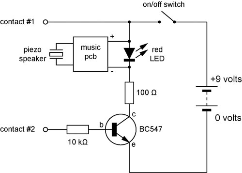
The cut on a fader is fundamentally different from a transform. It is not an instantaneous on/off switch; rather, it features a gradual slope that can range anywhere from a few hundred microseconds to tens of milliseconds. This duration...
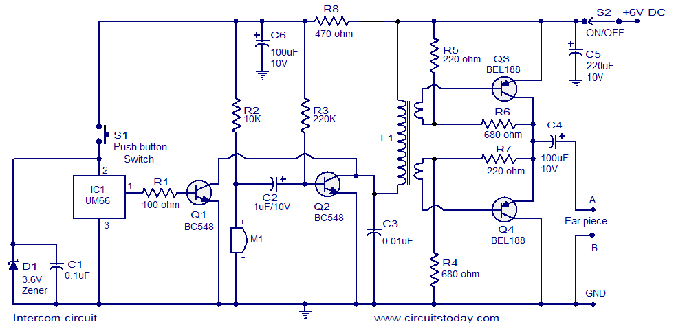
A straightforward intercom circuit designed using transistors. It does not require a changeover switch and can be used similarly to a telephone. This intercom circuit utilizes transistors to facilitate communication between two or more stations without the need for complex...
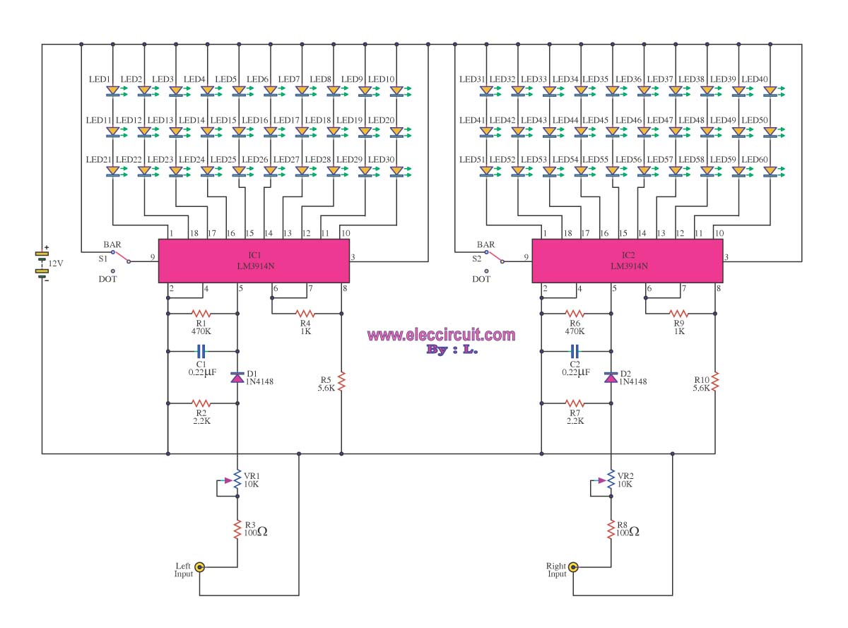
A VU meter is utilized to display the power level of audio signals and also serves as an aesthetic element. When purchasing a VU meter kit from an electronics store, options include assembling various parts independently or selecting a...
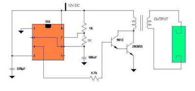
Fluorescent tubes contain mercury, which poses health risks. Improper disposal of these tubes is harmful to both the environment and health; therefore, recycling is a beneficial option. The 555 timer IC is utilized to generate a square wave voltage...
Warning: include(partials/cookie-banner.php): Failed to open stream: Permission denied in /var/www/html/nextgr/view-circuit.php on line 713
Warning: include(): Failed opening 'partials/cookie-banner.php' for inclusion (include_path='.:/usr/share/php') in /var/www/html/nextgr/view-circuit.php on line 713