
Common Collector Colpitts Oscillator

Once this is established, it is necessary to isolate the LC circuit from the base in terms of DC, which can be accomplished using a capacitor with a value significantly higher than the tuning capacitors. The supply must connect directly to the collector, as well as the divider, to provide a path for standing current in the transistor. Therefore, the top capacitor should be removed. The divider should connect directly to the base, as indicated, but both the inductor (L) and the tuning capacitor (Cs) need to be coupled to the base via a capacitor. Without this capacitor, the inductor will short out the bottom resistor in the divider chain, preventing proper biasing of the transistor. Consequently, the leftmost capacitor should be removed, and the inductor and the "top" capacitor should be disconnected from the base. Instead, they should be connected to a capacitor, with the other side of the capacitor connected to the base.
The frequency of oscillation will be the resonant frequency of the inductor in parallel with the two series capacitors. The formulas for capacitors in series and for parallel LC resonance can be found online. It is important not to use excessively large capacitor values; microfarads are preferred over millifarads. Capacitors suitable for resonating can be challenging to find in large values, and electrolytic capacitors are not appropriate for this application. If the oscillator operates but produces a poor waveform, a small resistor placed between the emitter and the junction of the two capacitors forming Ct may improve performance. However, this resistor should not be too large, or the oscillator may cease to function.
Regarding the output stability, it is noted that there is 6V after the divider, yet the output remains unstable. Despite achieving approximately 1 kHz with the selected values for L and C, the output is only about 987 mV instead of the desired 3V peak. Adjusting the value of the capacitor connected directly to the base may influence the output voltage. Further modifications may be necessary to achieve the desired output level.
To enhance the performance of the Colpitts oscillator, the following considerations should be taken into account:
1. **Component Selection**: Ensure that the BJT is rated for the required frequency and power levels. The choice of inductor (L) and capacitors (C) should be optimized for the desired oscillation frequency, keeping in mind the quality factor (Q) of the components used.
2. **Biasing Network**: The potential divider should be carefully calculated to ensure that the base-emitter junction is properly biased. The resistors in the divider should be selected to provide adequate base current while minimizing loading effects on the oscillator circuit.
3. **Capacitor Values**: The capacitors used in the LC network should be chosen based on the desired resonant frequency. The formula for resonant frequency \( f = \frac{1}{2\pi\sqrt{LC}} \) can be utilized to determine suitable values for L and C.
4. **Output Coupling**: The output voltage can be influenced by the coupling capacitor value. A larger coupling capacitor may allow for a higher output voltage swing but could also affect the frequency response. Experimentation with different capacitor values may be necessary to achieve the desired 3V peak output.
5. **Load Considerations**: The load connected to the output can affect the stability and amplitude of the output signal. Ensure that the load does not draw excessive current, which could lead to instability in the oscillation.
6. **Feedback Path**: The feedback path from the output to the base must be adequately designed to maintain oscillation. Ensure that the phase shift around the loop is appropriate for sustained oscillation.
By addressing these factors, the performance of the Colpitts oscillator can be optimized to achieve the desired frequency and output voltage.Design a Colpitts Oscillator in a common collector configuration using a single BJT. Provide base current to get the transistor operating properly, and you can do this using a potential divider (between Vcc and gnd): use resistor values as high as possible (bearing in mind the loading effect of the base current) in order not to load the LC circuit too much, and aim for a base voltage of about half the supply. Once you`ve done this you`ll need to isolate the LC circuit from the base, dc-wise, and you`d do this using a capacitor (whose value is much higher than the tuning capacitors). No, the supply must connect directly to the collector, as well as the divider - there needs to be a path for standing current in the transistor.
So delete the top capacitor. The divider should connect directly to the base, as you`ve shown, but both the L and the Cs need to be coupled to the base via a capacitor. If you don`t have this capacitor, the L will short out the bottom resistor in the divider chain, and you`ll not be biasing the transistor correctly.
No, remove the leftmost capacitor. Disconnect the L and "top" C from the base. Connect them both to a capacitor, and connect the other side of the capacitor to the base. Hope that`s clear! The frequency is the resonant frequency of the inductor in parallel with the two series capacitors. The formula for capacitors in series and for a parallel LC resonance is in Google. Don`t go too wild with the "large enough": think microfarads, not millifarads. Capacitors suitable for resonating can be inconvenient in large values: electrolytics won`t suit this job. If you get your oscillator to work, but with a rotten waveform, a small resistor in the lead between the emitter and the junction of the two capacitors forming Ct may help.
Do not make this too big, or the oscillator will not run any more. from the divider i know that there is 6V after the divider, but i dnt understand why my output is not stable. Also using these values, for L and C, ive managed to get 1kHz as i wanted initially, but how do i get a 3v peak output well i changed the values and im gettin about 987mV at the output.
would changing the value of the capacitor which is connected directly to the base effect the output or what would i need 2 change in order to get 3v peak output 🔗 External reference
Related Circuits
This circuit is a conventional Pierce type oscillator that utilizes a JFET. It employs fundamental mode crystals and demonstrates good performance and reliability when a low noise JFET is used. The feedback is regulated by the capacitance C1, which...
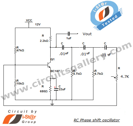
This section introduces a transistor oscillator circuit known as the RC Phase Shift Oscillator. An oscillator is an electronic circuit that functions as a sine wave generator, requiring only a DC power supply. It is commonly used in variable...
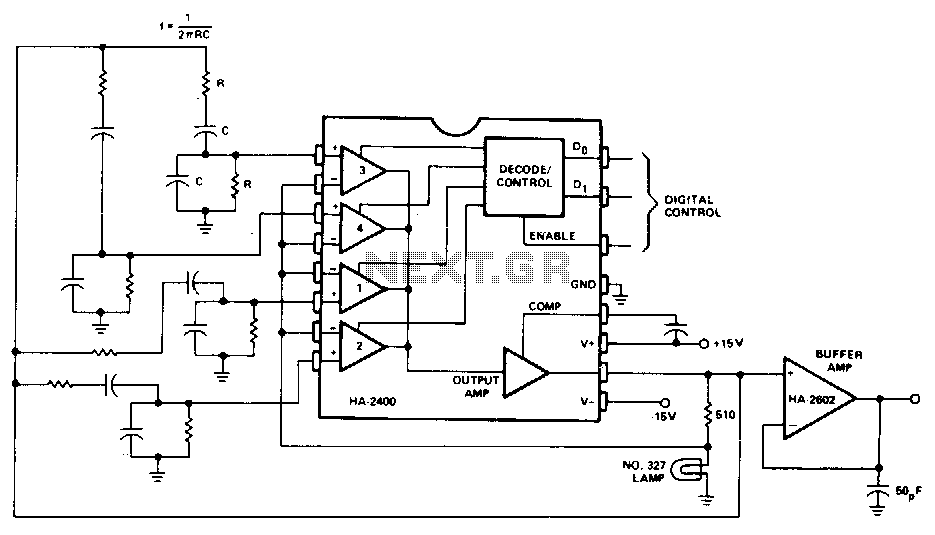
A Wien-bridge oscillator can be made variable by utilizing two frequency-determining components that are adjusted simultaneously with high tracking accuracy. However, high-quality tracking potentiometers or variable capacitors are often costly and challenging to procure. To circumvent the need for...
This unit would be mounted in a small plastic or preferably metal box, with a 9V battery, level control, a male XLR connector (same as on a mic) and a switch. Current drain is low, since the circuit only...
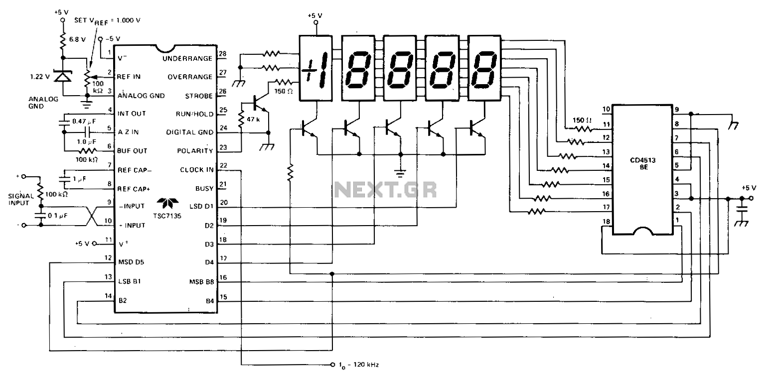
A Teledyne TSC7135 digital voltmeter (DVM) chip is utilized to control a multiplexed 5-digit display. To facilitate common cathode drive, a CD4513BE CMOS integrated circuit (IC) functions as a segment driver, with selection controlled by pins 17-20 of the...
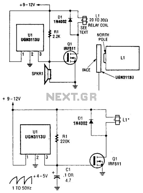
Although not intended for this application, a Hall-effect switch can be utilized as the foundation for an unconventional oscillator. The oscillator can be reconfigured, as illustrated in Fig. B, to enable the circuit's oscillating frequency to be regulated through...