
Unusual Hall-Effect Oscillators Circuit
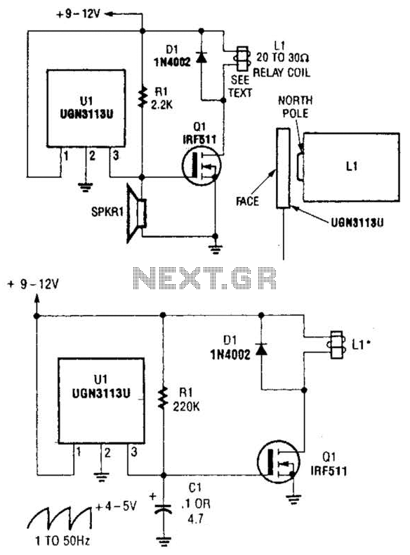
The proposed oscillator circuit leverages the properties of the Hall-effect switch, which typically detects magnetic fields but can also generate oscillations under specific configurations. In this setup, the Hall-effect switch is integrated into a feedback loop that influences its own switching behavior, resulting in oscillatory output.
The RC network, composed of resistor R1 and capacitor C1, plays a crucial role in determining the frequency of oscillation. The time constant of the RC network, defined as τ = R1 * C1, directly influences the charge and discharge rates of the capacitor, thereby affecting the frequency of the oscillations produced by the circuit. The oscillation frequency (f) can be approximated by the formula f = 1 / (2πτ), indicating that increasing the resistance or capacitance will lower the frequency, while decreasing them will raise it.
In practical applications, the Hall-effect switch oscillation circuit can be employed in various scenarios, including signal generation, timing applications, and even as a simple clock generator for digital circuits. The simplicity of the design, combined with the ability to easily adjust the frequency through the RC components, makes this circuit a versatile option for engineers seeking to implement oscillatory behavior in their designs.
When implementing this circuit, careful consideration must be given to the specifications of the Hall-effect switch, as well as the values chosen for R1 and C1, to ensure stable oscillation and desired frequency output. Additionally, the layout of the circuit should minimize noise and interference, which can affect the performance of the oscillator. Although not intended for this application, Hall-effect switch can be used as the basis for a rather unusual oscillator. The oscillator can be reconfigured, as shown in Fig. B, to allow the circuit`s oscillating frequency to be controlled via an RC network, comprised of Rl and CI. 🔗 External reference
Related Circuits
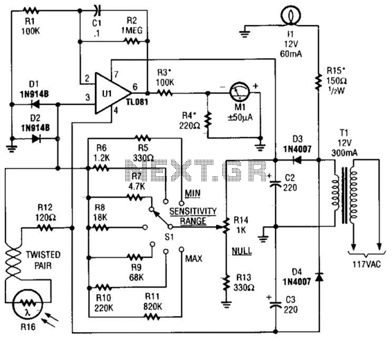
The Meter Ml is a +/-50-uA zero-center D'Arsonval meter movement driven by Ul, a TL081 FET op amp, through R3. The gain of Ul is set to 11 using resistors R1 and R2, while capacitor C1 restricts the bandwidth...
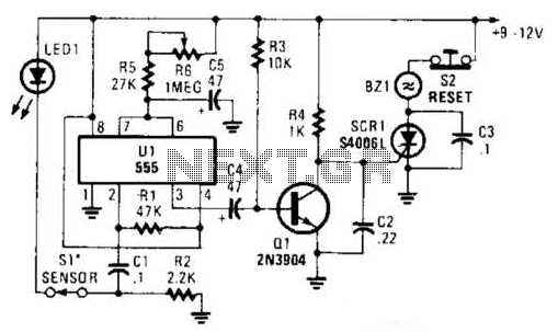
The alarm circuit utilizes a single 555 oscillator/timer (U1) that functions in both the alarm-trigger circuit and the entry-delay circuit. In this configuration, the trigger input of U1 at pin 2 is maintained in a high state through resistor...
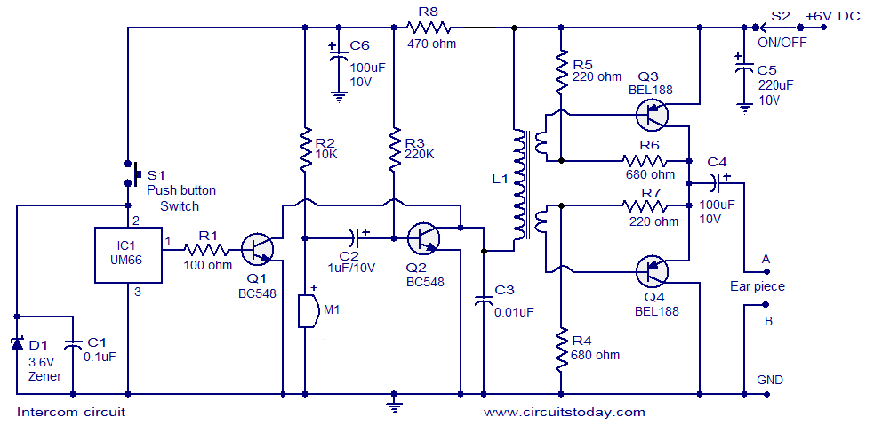
A straightforward intercom circuit designed using transistors. It does not require a changeover switch and can be used similarly to a telephone. This intercom circuit utilizes transistors to facilitate communication between two or more stations without the need for complex...
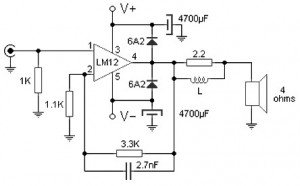
Almost all audio power amplifiers utilize integrated circuit amplifiers, such as the M12CLK, which is a power operational amplifier. This amplifier allows for an output stage that operates at an impedance of 2 ohms and provides a power gain...
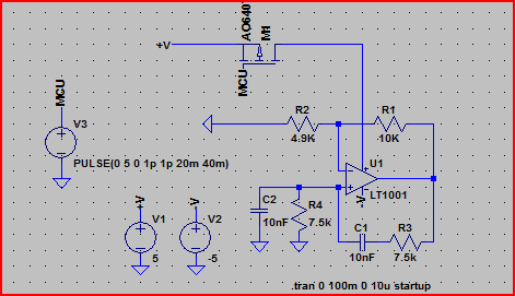
Construct a Wien bridge oscillator that operates at 2.1 kHz and can be activated by a transistor. The inclusion of a transistor switch in the circuit allows for control of the oscillator's operation from a PIC microcontroller. However, during...
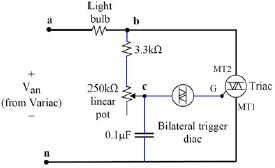
The refrigerator turned on, causing the lights to brighten. Initially, it seemed like an illusion, but after observing multiple cycles, the phenomenon persisted. When the microwave was activated, the lights dimmed. The refrigerator's operation appeared to influence the brightness...
Warning: include(partials/cookie-banner.php): Failed to open stream: Permission denied in /var/www/html/nextgr/view-circuit.php on line 713
Warning: include(): Failed opening 'partials/cookie-banner.php' for inclusion (include_path='.:/usr/share/php') in /var/www/html/nextgr/view-circuit.php on line 713