
Common emitter amplifier works a

The common emitter amplifier is a widely used configuration in analog electronics, primarily due to its ability to provide significant voltage gain. In this setup, the transistor operates in its active region, where it can effectively amplify AC signals. The common emitter configuration is characterized by its input being applied to the base terminal, while the output is taken from the collector terminal, with the emitter typically grounded.
The input signal is coupled to the base of the transistor through a coupling capacitor, which blocks any DC biasing present in the signal source. The transistor's base-emitter junction is forward-biased, allowing current to flow through the transistor. The amplification factor of the transistor, often represented by the current gain (β), dictates the relationship between the input current and the output current.
The output voltage across the load resistor (RL) is influenced by the supply voltage (VCC) and the collector-emitter voltage (VCE). The output can be expressed mathematically as UR = VCC - ICRC, where URC represents the voltage across the collector resistor (RC). As the input signal varies, the transistor's collector current (IC) also changes, leading to variations in the output voltage across RL.
It is essential to note that in a common emitter amplifier, the output signal is inverted relative to the input signal. This phase inversion is a critical characteristic of the configuration, making it suitable for applications requiring signal inversion. The output waveform can be analyzed over multiple cycles to observe the periodic behavior of the amplifier, confirming the inverse relationship between the input and output signals.
In summary, the common emitter amplifier is an effective circuit for amplifying AC signals, providing both voltage gain and phase inversion. Proper biasing and component selection are crucial for ensuring optimal performance and stability in various electronic applications. Common emitter amplifier works a Signal by the common emitter inverting amplifier output signal amplification unit posterior pole circuit, it works as shown. When analyzed, we can change the input signal curve, that is the end of the current input curve. When 1/4 period, tended to increase the current state, then according IC- 18IB amplification transistor, also known as the current tends to increase, according to Ohms law URC ICRC, seven f. The URC f, that it by the output voltage on the load RL UR, VCC- URC available Seven t, URC t, Vcc unchanged, Uk, J.
Ie the output shown in Figure 1-7 (a) shown in the curve. Other cycle and so on in FIG. (B) (c) (d) as shown, we can see, the output voltage and the input voltage of opposite phase.
Related Circuits
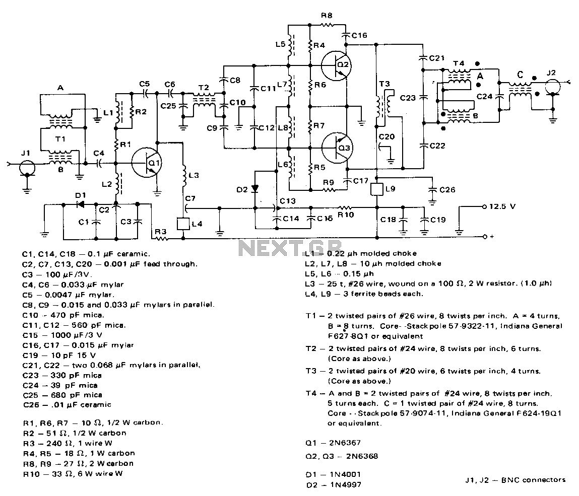
This amplifier employs a 2N6367 transistor as a driver along with a pair of 2N6368 transistors. The 2N6367 is rated for a maximum output of 9 W (PEP) and is required to deliver 5 W (PEP) at 30 MHz,...
All resistors have a tolerance of 5 or 10 percent and are rated for 1/4 watt. All capacitors have a tolerance of 10 percent and are rated for 35 volts or higher. This circuit effectively amplifies the output of...
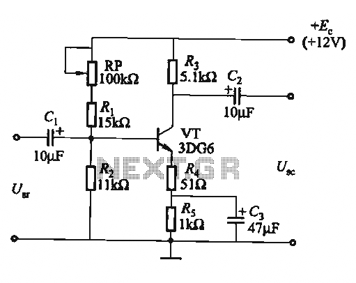
The circuit is a bias circuit for automatic stabilizers that maintains a stable quiescent operating point with good thermal stability. It utilizes a three-pole tube with an NPN type transistor, characterized by a small Iceo. An adjustment potentiometer, RP,...
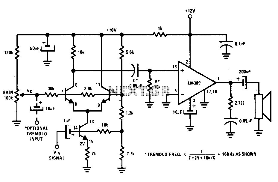
The transistors create a differential pair with an active current-source tail. This configuration, referred to as a variable-transconductance multiplier, produces an output that is proportional to the product of the two input signals. The multiplication effect arises from the...
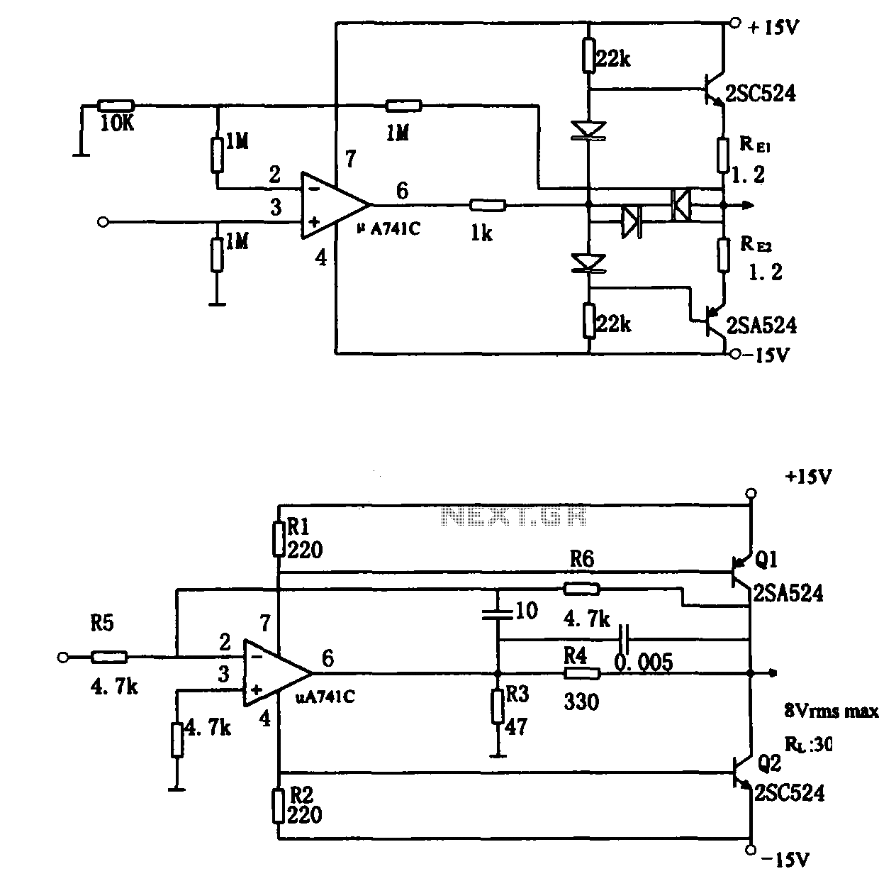
The direct coupling audio power amplifier utilizes an integrated operational amplifier. There are typically two practical configurations. The first configuration, depicted in (a), features a circuit structure that includes the output of the operational amplifier and a complementary symmetry...
In terms of AC signals, the base is connected to the ground through capacitor C3. Consequently, both the input and output are linked to the base, forming a common base amplifier configuration. The common base amplifier is a type of...