
Common ground for different voltages in relay circuit
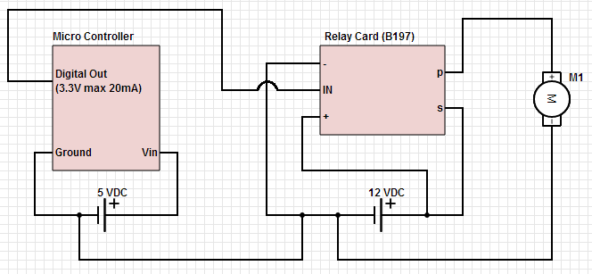
To achieve the control of a 12 VDC device using a microcontroller and a relay card, a circuit design must incorporate several key components. The microcontroller, which serves as the control unit, will send a signal to activate or deactivate the relay. The relay acts as an electrically operated switch that can handle the higher voltage and current needed to power the 12 VDC device.
The circuit typically consists of the following components:
1. **Microcontroller**: This device generates the control signal. Common choices include Arduino, PIC, or STM32 microcontrollers. The microcontroller's output pin is connected to the relay module's input pin.
2. **Relay Module**: The relay module consists of one or more relays capable of handling the 12 VDC load. It usually includes an opto-isolator for safety and to protect the microcontroller from back EMF generated by the relay coil. The relay coil requires a 12 VDC supply for operation, which can be provided from the same power source as the device being controlled or from a separate regulated power supply.
3. **Power Supply**: A 12 VDC power supply is necessary to power both the relay and the connected device. This power supply should be capable of providing sufficient current to meet the demands of the device being controlled.
4. **Protection Diode**: A flyback diode should be placed across the relay coil terminals to prevent voltage spikes (back EMF) when the relay is deactivated. This diode ensures that the current generated by the collapsing magnetic field does not damage the microcontroller.
5. **Control Circuit**: The microcontroller's output pin is connected to the input of the relay module, which may include a transistor to amplify the control signal. When the microcontroller sends a high signal, the transistor turns on, energizing the relay coil and closing the switch, allowing current to flow to the 12 VDC device.
6. **Load**: The 12 VDC device that needs to be controlled. When the relay is activated, the device receives power and operates as intended.
The circuit can be designed on a breadboard for prototyping or laid out on a printed circuit board (PCB) for a more permanent solution. Proper attention should be given to the layout to minimize noise and interference, especially if the microcontroller operates at lower voltages. Additionally, the relay's specifications should match the requirements of the load to ensure reliable operation.
In conclusion, this setup allows for effective control of a 12 VDC device using a microcontroller through a relay, enabling automation and remote control capabilities in various applications.Hello, My goal is to control a 12 VDC device (on/off) from a microcontroller using a relay card. The relay needs 12 VDC operating power (I use the.. 🔗 External reference
Related Circuits
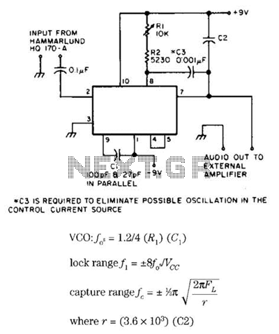
Useful for narrowband frequency modulation (NBFM) reception on older shortwave receivers that lack this capability, this circuit employs a phase-locked loop (PLL) integrated circuit, specifically the N565N. It was originally designed for use with an old Hammarlund HQ-170 receiver,...
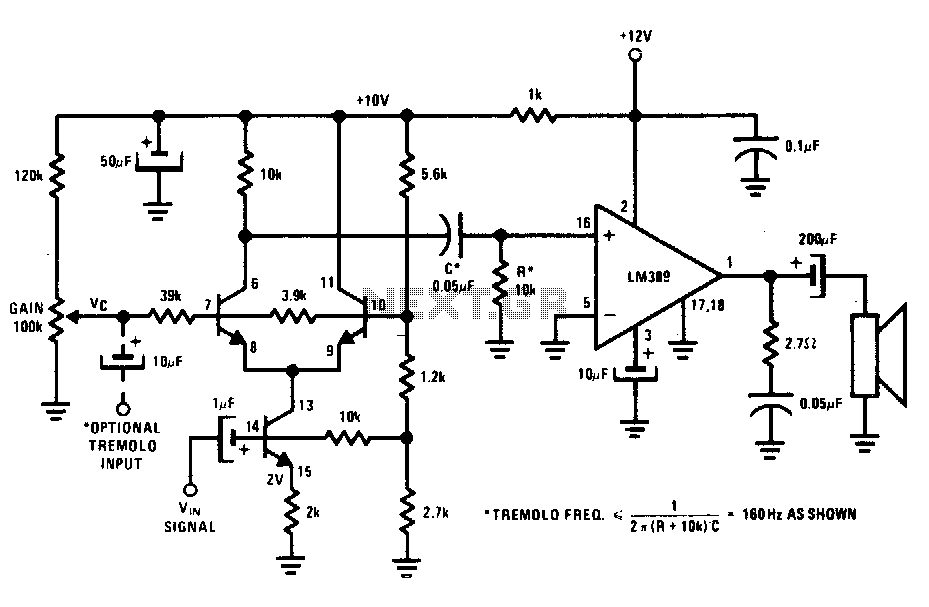
The transistors create a differential pair with an active current-source tail. This configuration, referred to as a variable-transconductance multiplier, produces an output that is proportional to the product of the two input signals. The multiplication effect arises from the...

This device functions as a convenient tool for testing infrared (IR) remote control transmitters used with televisions, VCRs, and similar devices. The IR signals emitted from a remote control are detected by the IR sensor module within the tester,...
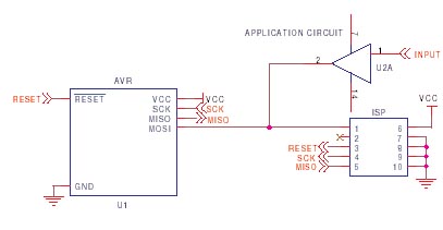
It is crucial to design the PCB layout correctly to enable seamless In-System Programming (ISP) of AVR microcontrollers. This guide addresses common issues encountered and provides typical AVR ISP circuit schematics. It focuses on Serial Programming, known as ISP,...
This circuit serves as a decorative element or indicator, featuring adjustable flashing or dancing speeds of LEDs and the ability to create various light patterns. It consists of two astable multivibrators: one formed by transistors T1 and T2, and...
In various electronic applications, it is necessary to switch or control high voltages or high currents. In such instances, electromagnetic or solid-state relays may be utilized. For example, these relays can control home appliances using low-power electronic circuits. An...
Warning: include(partials/cookie-banner.php): Failed to open stream: Permission denied in /var/www/html/nextgr/view-circuit.php on line 713
Warning: include(): Failed opening 'partials/cookie-banner.php' for inclusion (include_path='.:/usr/share/php') in /var/www/html/nextgr/view-circuit.php on line 713