
AVR ISP Circuit Schematics
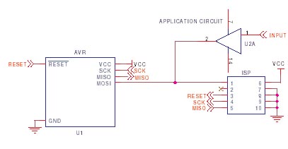
The design of a PCB for AVR microcontrollers necessitates careful attention to the ISP circuit layout to ensure reliable programming and operation. The ISP circuit typically includes essential components such as bypass capacitors, pull-up resistors, and the necessary connections to the microcontroller's programming pins. The programming lines, specifically SCK (Serial Clock), MISO (Master In Slave Out), and MOSI (Master Out Slave In), should be configured to minimize interference and maintain signal integrity.
For optimal performance, the capacitor connected between the Reset and Ground pins should have a low value, ideally below 10nF, to prevent unwanted delays in the programming process. The resistor from Reset to VCC plays a critical role in ensuring that the microcontroller powers up correctly before programming begins. The recommended resistor values can vary, but a standard range of 4.7kΩ to 10kΩ is commonly used.
In scenarios where the programming pins are also used by the application, it is advisable to include isolation resistors to prevent interference with the programming signals. This is particularly important in UART applications where TXD and RXD lines may conflict with programming operations. A multiplexer may be employed if higher current requirements arise, facilitating the management of multiple signal paths.
The choice between a 6-way and 10-way ISP header should be made based on the specific requirements of the project and the available programming tools. While both header types are compatible with the AVR microcontroller, the additional ground connections in a 10-way header can enhance noise immunity during programming, which is beneficial in electrically noisy environments.
Furthermore, the integration of the JTAG interface into the PCB design allows for advanced debugging capabilities. Care must be taken to configure the JTAG lines correctly, ensuring that the JTAGEN fuse is set and that isolating resistors are used if the JTAG pins are repurposed for general I/O tasks. This flexibility enhances the overall utility of the PCB, allowing for both programming and debugging functionalities.
In summary, a well-structured PCB layout for AVR microcontrollers, incorporating both ISP and JTAG interfaces, will significantly contribute to the reliability and efficiency of the programming process, ultimately leading to a more robust electronic design.It is important to layout your PCB correctly to allow trouble free In System Programming of AVR microcontrollers. This guide covers the usual problems that are encountered and typical AVR ISP circuit schematics. This guide covers Serial Programming, which is commonly called ISP, not JTAG programming which uses a different connector and algorithm.JTAG interface is used for debugging on larger
AVR devices (40-pin plus) and can be used for programming as well. Most Kanda AVR programmers also support JTAG. Please see below for AVR JTAG interface. In System Programmers have different amounts of "drive" depending on their price and design, so for maximum flexibility in choosing a programmer, err on the side of caution unless you have compelling reasons for fitting large capacitors and low value resistors. The AVR ISP connector can be either 6 or 10-way, but this makes no difference to your circuit layout.
10-way connectors have more Ground lines to improve noise immunity during programming. The simplest AVR ISP circuit is shown here, with some notes. Ground and VCC must be connected to programmer, either to power programmer or to provide a reference voltage for lower voltage circuits. The capacitor connected between Reset and Ground, and the resistor from Reset to Vcc should be fitted to give a slight delay to allow AVR to power up properly.
These values are not critical, but if they are too large then the ISP programmer will need to be slowed down. The programming lines (SCK, MISO and MOSI) are best left just for programming, but if these pins must be used by the application, then resistors should be used to isolate the application circuitry, typically 4K7.
This is especially important if TXD/RXD are used for programming, as UART chips tend to hold the lines. This should be fine for SPI or UART use or where pins are inputs but if you have to use these lines for higher current, then a multiplexer circuit may be needed, see STK200 schematics.
Capacitors on the programming lines can cause problems, especially on SCK. If they have to be fitted, then they should be below 10nF and fitted as close as possible to AVR microcontroller pins. Some low cost programmers will have problems with even a 10nF capacitor on SCK or MOSI, so smaller is better.
Atmel recommend that a diode is fitted between Reset and Vcc as shown here, but we have not found it necessary in practice. Note their recommended resistor and capacitor values are slightly different, but these values are not critical.
A capacitor between 10nF and 100nF and a resistor between 4K7 and 10K will be fine. Most engineers use either a 10-way ISP Header or a 6-way ISP header on their PCB. Both formats are 0. 1" (2. 54mm) dual-in-line pin headers with a keyway for orientation. Most programmers use 10-way header but Atmel have swapped to 6-way. Adapters are available to swap from 10-way programmer leads to 6-way headers. JTAG interface is also 0. 1" (2. 54mm) pin header. JTAGEN fuse must be set for JTAG interface to work. The JTAG lines can be used for other JTAG devices without problems but if JTAG pins are used as general I/O, then they should be fitted with isolating resistors just like ISP lines. Kanda programmers use an adapter to swap to standard Atmel JTAG interface shown - target layout view.
🔗 External reference
Related Circuits
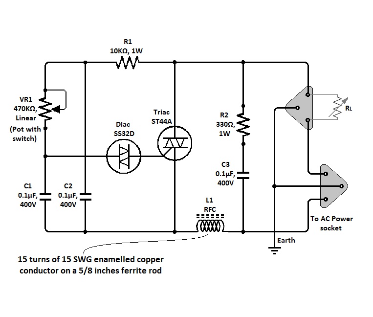
The circuit of a simple triac light dimmer can be used to dim incandescent lamps directly from AC mains. It is easy to construct and requires very few components. A potentiometer is utilized to control the load power or...
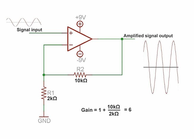
An amplifier is a device that increases the voltage in a circuit. The simplest type is an operational amplifier, and this video will demonstrate how these devices function and how to implement them in electronic applications. As an example,...
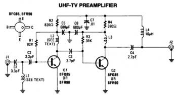
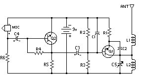
This is a low-cost, antenna-mounted UHF TV pre-amplifier circuit that can provide more than 25 dB of gain. The first stage of the pre-amplifier is biased for optimum gain. L1 and L2 are strip line equivalents with a length...
This circuit is designed to achieve exceptional popularity, as evidenced by its record-breaking views and comments on the referenced website. As of May 3, 2013, it has garnered 760,191 views and 412 comments, with 116 views recorded on that...
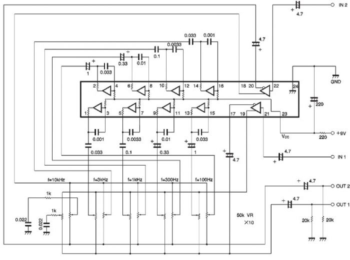
The BA3822 is a five-point stereo graphic equalizer integrated circuit that operates with two channels. Each channel can independently set five center frequencies using external capacitors. This integrated circuit supports a wide operating power supply voltage range (VCC =...
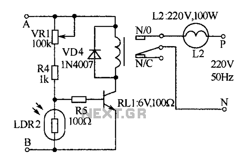
The receiver, as depicted in the figure, assists patients in avoiding missed audio signals during the daytime. The receiver operates independently, and the lighting will automatically turn off. At night, the lighting signal receiver activates simultaneously with the patient's...