
interfacing relay 8051 keil c
In the context of electronic circuits, relays serve as crucial components for controlling high power devices while maintaining the integrity of low power control circuits. The operation of an electromagnetic relay is based on the principles of electromagnetism. When the relay coil is energized, it generates a magnetic field that attracts a movable armature, closing or opening the contacts of the relay. This action allows the relay to control the flow of electricity in a high power circuit without exposing the low power control circuit to high voltages or currents.
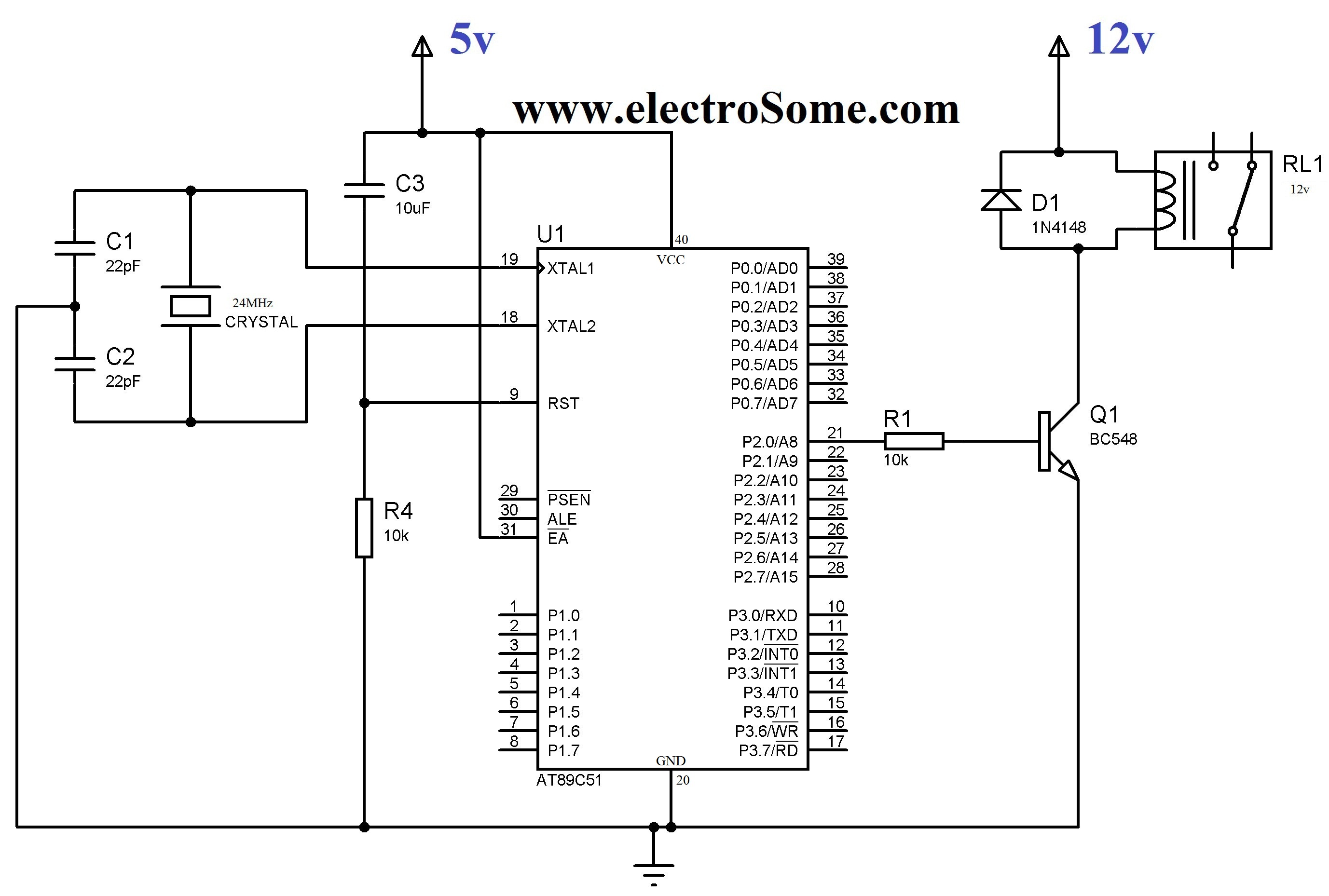
To implement a relay in a circuit, a transistor is often employed as a switch. The transistor acts as an intermediary, amplifying the current from the microcontroller to drive the relay coil. In this configuration, a resistor is placed in series with the base of the transistor to limit the current flowing into it, ensuring that the transistor operates within its safe limits. The relay coil is connected to a higher voltage supply, which allows it to draw the necessary current to activate the relay.
It is essential to consider the specifications of both the relay and the microcontroller when designing the circuit. The relay's coil voltage and current ratings must match the supply voltage used, while the transistor must be chosen based on its ability to handle the required current and voltage levels. Additionally, flyback diodes are commonly used in relay circuits to protect the transistor and microcontroller from voltage spikes generated when the relay coil is de-energized.
In summary, the integration of relays into electronic circuits provides a reliable means of controlling high power devices, ensuring that low power control systems remain safe and effective. Proper circuit design, including the use of transistors and protective components, is vital for the successful implementation of relay-based control systems.In some electronic applications we need to switch or control high voltages or high currents. In these cases we may useelectromagnetic or solid state relays. For example, it can be used to control home appliances using low power electronic circuits. Anelectromagneticrelayis a switch which is used to switch High Voltage or Current using Lowpower circuits. It magnetically isolates low power circuits from high power circuits. It is activated by energizing aelectromagnet, coil wounded on a soft iron core. For detailed working of relay please visit this page. A relay should not be directly connected to a microcontroller, it needs a driving circuit due to the following reasons. A microcontroller will not able to supply current required for the proper working of a relay. The maximum current that A89C51 microcontroller can source or sink is 15mA while a relay needs about 50 100mA current.
Transistor is wired as a switch. which drives the relay. When the first pin of port P2 goes high the base current flows through the 10k resistor. This in turn switches the transistor ON. The relay gets enough current through the 12v supply to switch the secondary circuit ON. 🔗 External reference
Related Circuits

This circuit utilizes a Power Battery Terminal (PBT) to facilitate simple relay output and auxiliary power connections. An LED on each channel serves to indicate the status of the relay. Berg pins are provided for connecting power and trigger...
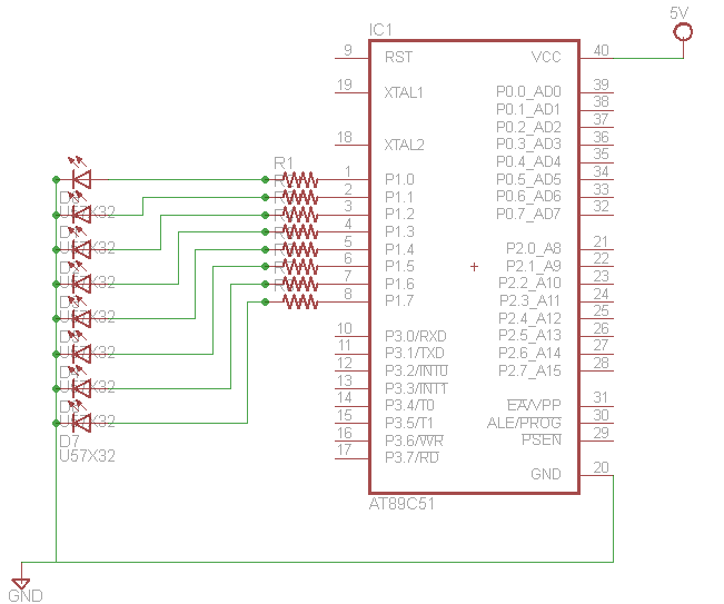
Learn how to interface LEDs with the 8051 Microcontroller. Download free source code and circuit diagram of the P89V51RD2 Microcontroller. Interfacing LEDs with the 8051 microcontroller is a fundamental project that serves as an excellent introduction to microcontroller applications. The...
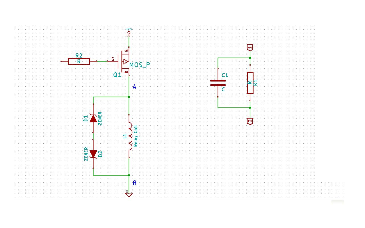
Although this may be a basic question, there is still some struggle with it. In this schematic, two zener diodes D1 and D2 are connected back-to-back across relay coil L1. The breakdown voltage (BVds) is -30V for Q1. The...
This simple circuit, as shown in the schematic diagram, activates a switch using sound. It can be utilized for various applications, such as an automatic sound-controlled disco light or a car's LED light show. The transistor Q1 amplifies the...
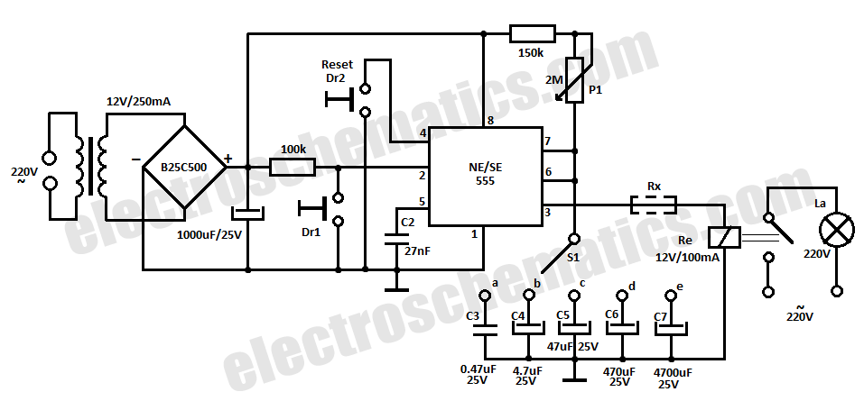
This time delay relay circuit is constructed using the NE/SE555 integrated circuit, manufactured by Intersil, which features a precision timer. The circuit exhibits stability against temperature variations. The NE/SE555 integrated circuit is a versatile timer used in various applications, including...
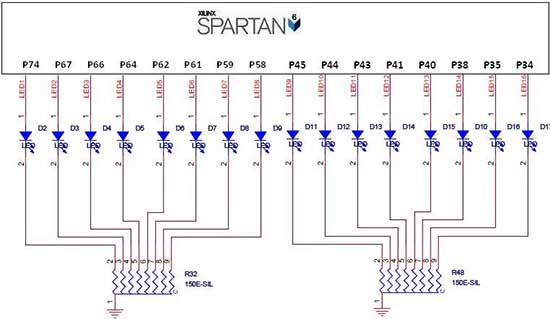
The Spartan-6 board features 16 LEDs connected to FPGA I/O pins, as detailed in the table below. The cathode of each LED is connected to ground through a 330-ohm resistor. To illuminate a specific LED, the corresponding FPGA control...
Warning: include(partials/cookie-banner.php): Failed to open stream: Permission denied in /var/www/html/nextgr/view-circuit.php on line 713
Warning: include(): Failed opening 'partials/cookie-banner.php' for inclusion (include_path='.:/usr/share/php') in /var/www/html/nextgr/view-circuit.php on line 713