
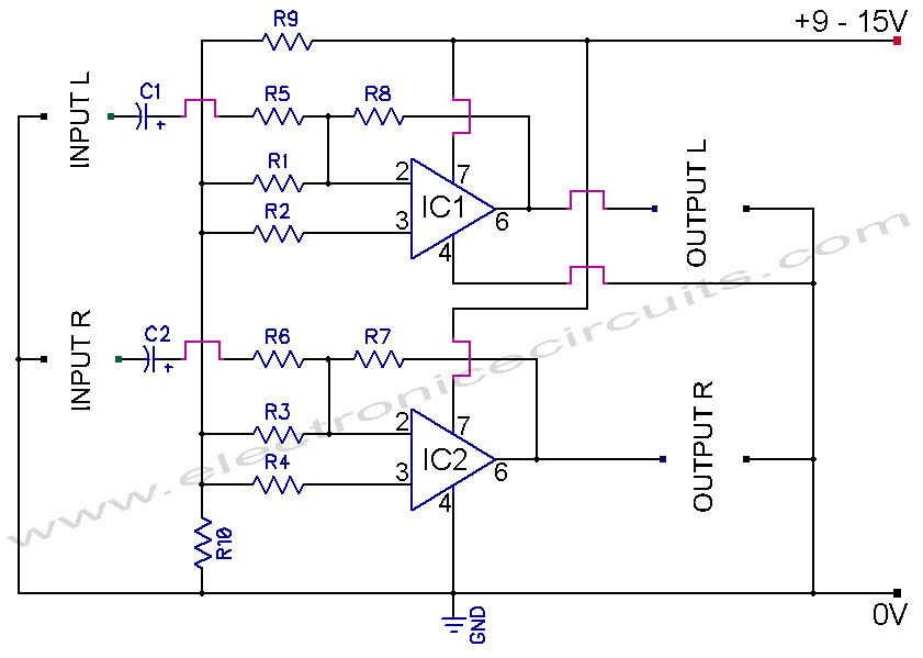
Common mode input voltage of the differential amplifier circuit diagram up l00V

The circuit diagram described features a design capable of handling a common mode input voltage with a differential range of up to 100V. Such a configuration is essential in applications where high voltage signals may be present, and it is crucial to maintain signal integrity while minimizing noise and interference.
In this circuit, the common mode voltage refers to the average voltage level present on both input lines, while the differential voltage is the voltage difference between these two lines. The ability to manage a common mode input voltage of 100V indicates that the circuit employs robust components designed to withstand high voltages without compromising performance.
Typically, this type of circuit may utilize instrumentation amplifiers or differential amplifiers that are specifically designed to reject common mode signals while amplifying the differential signal. Key components may include precision resistors, operational amplifiers, and possibly isolation techniques to ensure that the circuit operates safely and effectively under high voltage conditions.
In practical applications, such circuits are often found in industrial sensor systems, data acquisition systems, and communication devices where high-voltage signals need to be accurately measured or processed without distortion. Proper layout and shielding techniques are also critical in these designs to prevent electromagnetic interference (EMI) and ensure reliable operation. The enlarged circuit diagram would typically illustrate these components and their interconnections, providing a clear visual representation of the circuit's functionality. Common mode input voltage up to difference l00V enlarged circuit diagram:
Related Circuits
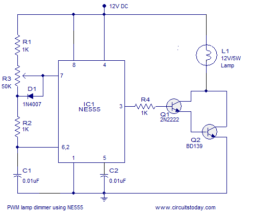
A simple PWM lamp dimmer using the NE555 timer IC. The 555 timer IC is configured as a variable duty cycle astable multivibrator to control the brightness of the lamp. The described circuit utilizes the NE555 timer IC, a versatile...
Equipment designed to detect changes associated with fire, monitor the integrity of their operations, and provide automatic control and transmission of information necessary to prepare the facility for fire, temperature, and light based on a predetermined sequence. The panel...
A new user has joined the forum and is seeking assistance with circuit design. They express a desire for guidance and acknowledge their inexperience in the subject. In circuit design, it is crucial to understand the fundamental components and their...
741 Stereo PreAmplifier Circuit Diagram. This preamp circuit provides better than 20dB gain in each channel. PARTS LIST R1 -.. The 741 stereo preamplifier circuit is designed to amplify audio signals with a gain of over 20 dB in each...
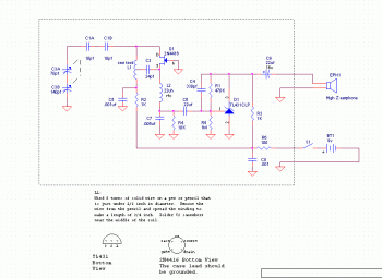
This is a very simple FM receiver built using only one transistor. It does not utilize any chips or other active components. The output is connected to earphones; an amplifier circuit is required if the radio is to be...
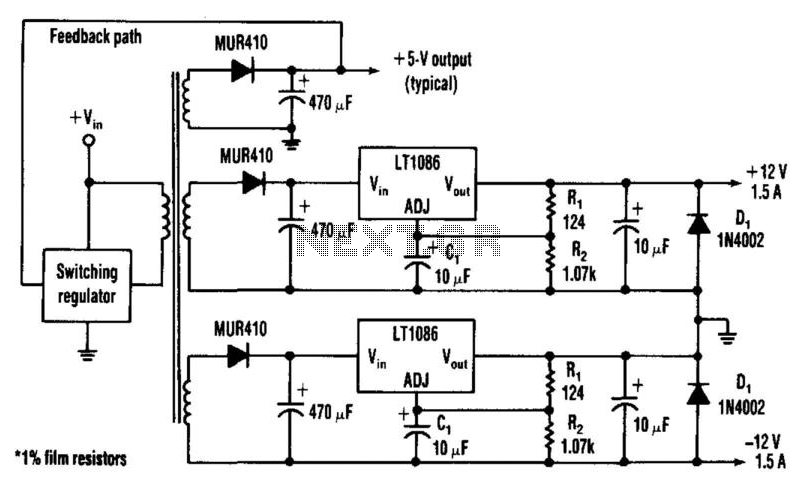
Many applications require highly efficient negative-voltage post regulators with low dropout voltage in switch-mode supplies. A method to achieve effective negative-voltage regulation is by utilizing a low-dropout positive-voltage regulator that operates from a well-isolated secondary winding of the switch-mode...