
One Transistor FM Receiver circuit diagram
The FM receiver circuit primarily consists of a single transistor functioning as the active amplification element. The simplicity of this design allows for easy construction and understanding of fundamental FM reception principles. The circuit typically includes a few passive components such as resistors, capacitors, and an inductor, which together form the necessary tuned circuit for signal reception.
In operation, the circuit receives FM signals through an antenna, which can be a simple wire. The antenna picks up radio frequency signals, which are then filtered and amplified by the transistor. The transistor is configured in a common-emitter or common-collector arrangement, depending on the desired output characteristics.
The output from the transistor is typically at a low level, suitable for direct connection to earphones. For applications requiring a louder output, such as driving a loudspeaker, an additional amplifier stage is necessary. This amplifier can be constructed using another transistor or an integrated circuit designed for audio amplification.
To enhance performance, the circuit may include additional components such as a variable capacitor for fine-tuning the frequency response, allowing the user to select different FM stations. Furthermore, bypass capacitors may be employed to stabilize the power supply and improve audio quality by reducing noise.
Overall, this simple FM receiver circuit serves as an excellent introduction to radio frequency electronics, demonstrating essential concepts such as signal amplification, tuning, and audio output interfacing.This is a very simple FM receiver which build based on one transistor only. No chip or another active component. The output is connected to earphones, you need an amplifier circuit if you want to listen the radio with a loudspeaker. 🔗 External reference
Related Circuits
Switching regulator subsystems intended for use as DC to DC converters. 3V to 40 Volt DC Converter circuit. The use of switching regulators is becoming more pronounced than that of linear regulators because the size reductions in new equipment...
This is a diagram of a car audio active loudspeaker utilizing the LF353 operational amplifier from National Semiconductor. For optimal performance, the NE5532 is recommended to split the audio signal into three frequency bands using an active filter. The...
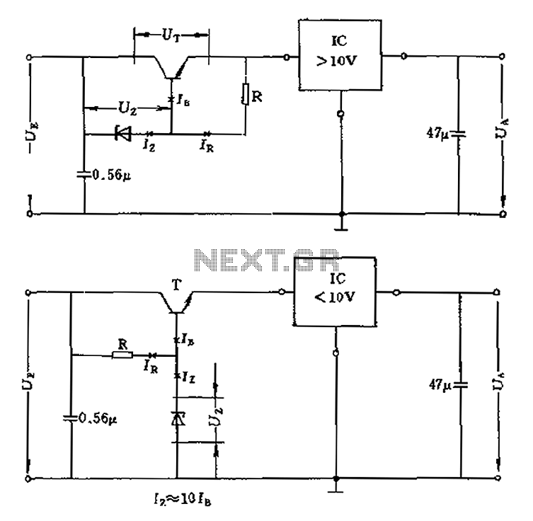
The voltage equation Ue = Ut + Ur + Ua indicates that the transistor voltage Ut will determine the maximum output voltage Ua. Additionally, Ur must be 2V. The voltage regulator's voltage value depends on the selection of Uz....
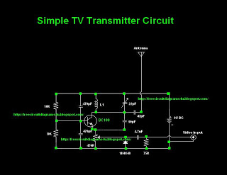
Many individuals inquire about TV transmitters. This document provides a useful circuit diagram that enables signal transmission over distances of 75 to 100 meters. The circuit diagram is not original but was provided by a colleague. Contributions of circuit...

This inverter circuit is designed to power electric razors, stroboscopes, flash tubes, and small fluorescent lamps using a 12-volt car battery. Unlike typical feedback oscillator inverters, this design features a separate oscillator from the output stage, allowing for easy...
A circuit diagram of the T1 is a low-impedance output transformer, featuring a 5000-8 ohm resistor. The T1 low-impedance output transformer is designed to match the output of audio amplifiers to the impedance of loudspeakers, ensuring optimal power transfer and...