
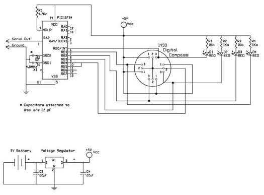
compass

The schematic design incorporates the diode bridge, which consists of four diodes arranged in a bridge configuration. This arrangement allows for the rectification of the power supply, ensuring that regardless of the cable orientation, the voltage polarity remains consistent and safe for the connected components. The RCX power supply section is designed to regulate the voltage to the necessary levels while providing the required current to operate the Dinsmore compass sensor effectively. The compass output select state machine is responsible for controlling which output from the Dinsmore sensor is active at any given time, enabling the sequential reading of the compass outputs. The compass power and output select section manages the power distribution to the Dinsmore sensor, ensuring that only one of the outputs is powered while the other remains inactive, thus conserving energy and preventing overload. Finally, the RCX sensor readings hardware interfaces directly with the RCX, processing the combined readings from the compass sensor to calculate the angle of orientation accurately. This comprehensive approach ensures that the compass sensor operates efficiently within the constraints of the RCX system while providing reliable directional readings.The goal was to make a compass sensor compatible with the RCX and have it only take one sensor input port to take a compass reading. We decided to use a Dinsmore analog compass part that has two outputs that need to be combined to determine the direction the compass is pointing.
With our design, it takes two readings by the RCX to get one complete reading from the compass sensor. Software then must combine those readings together to determine the angle the compass is pointing. We had to do it this way because of power demands by the Dinsmore part and power limitations of the RCX. We wanted to add hardware around the Dinsmore sensor to combine the two outputs into one RCX input. We first tried to put all the "inside/outside crossings" logic into hardware, but we found out the hard way that the RCX can only provide about 10mA of current.
It turns out we can only power 1/2 the Dinsmore compass sensor at a time. Rick Sammartino (RickSam from the Mindstorms website) who has been helping me all along, had and idea of reading one curve then the other. This fit well with powering one compass sensor then the other. The Dinsmore compass sensor has two outputs that need to be combined to know the direction you are pointing.
Figure 1 shows the compass outputs as they look across a 360 degree turn. It took me a while to make sense of the compass sensor outputs. To determine the outputs` values when pointed a particular direction, draw a verticle line at the angle you want the compass to point. The vertical line intersects with the two output curves only once per vertical line. These intersections are the two output values you can expect when the compass is pointing in that direction.
As you rotate the compass, you are basically sliding your vertical line left or right on the graph. As you rotate the Dinsmore compass, there are two angles where the output values are the same. One is above the 2. 5V center line, and the other is below the 2. 5V center line. We`ll call these the upper crossing and the lower crossing. Knowing these voltages are important to understanding the compass output. At any given orientation, one of the Dinsmore compass outputs is either above the upper crossing, or below the lower crossing while the other compass output is between the crossings (unless you are at one of the two crossover points). The output that is between the crossings is follows a fairly straight line, while the output outside the crossings does not.
The trick is to determining the direction the compass is pointing is to determine which output is outside the crossings, and then use the output that is inside the crossings to know the angle. We designed and debugged a "two reading" circuit shown in the schematic. The circuit has four major parts: RCX power supply, compass output select state machine, compass power and output select, and RCX sensor readings hardware.
We get the power we need to run the electronics in our sensor by setting the RCX sensor port type to light sensor. This makes the RCX output 7 volts at a maximum of about 10 mA of current. Every 3 milliseconds the RCX drops the power for about 1/10 of a millisecond to take a sensor reading.
The cables that connect sensors to RCX sensor inputs can be oriented one of two ways: cable pointing towards the IR port, or away from the RCX port. There are two terminals on an RCX sensor port. The RCX always sends power out one terminal and back in on the other terminal. When we connect a sensor with the cable pointing toward the RCX`s IR port, the power travels down one wire and comes back the other.
When we orient the cable the other way, the power flow is reversed. Reversing the power can be bad for electronics, and they certainly won`t work as planned. To allow the user to connect their sensor cable with either orientation we use something called a diode bridge to make sure the power always flows the correct direction. A diode bridge 🔗 External reference
Related Circuits
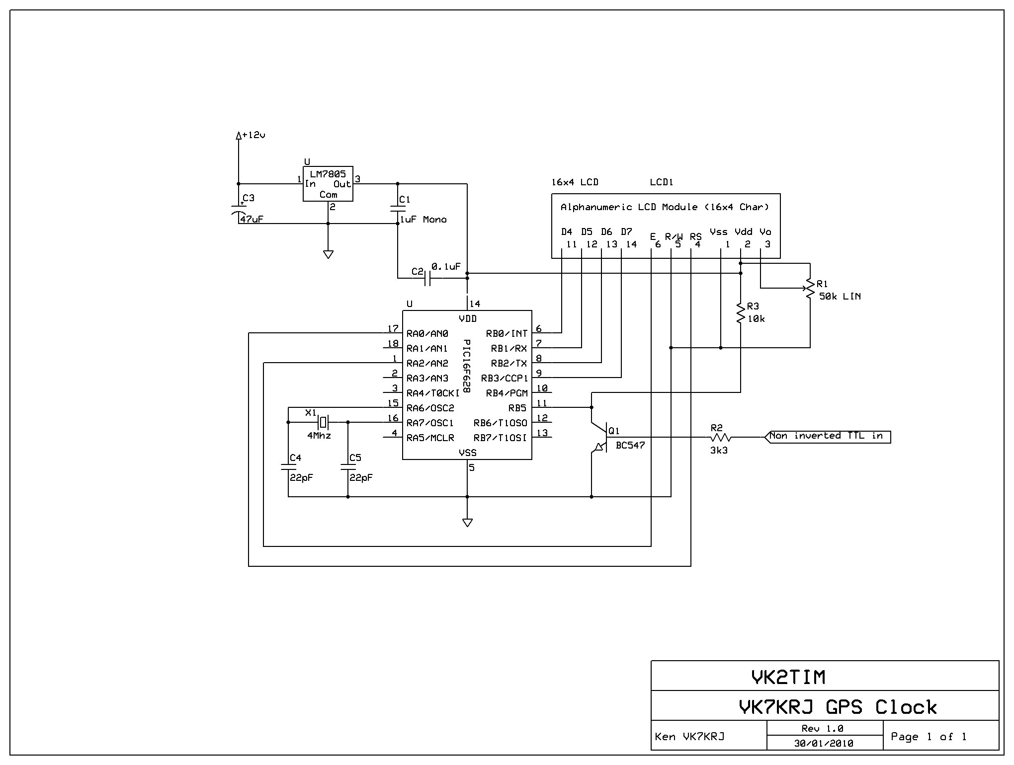
This project is a GPS-based clock that displays the current date, automatically adjusts for daylight saving time, shows current speed, maximum speed, and present heading in degrees relative to true north. The original firmware and concept were developed by...
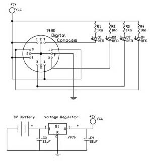
The first test circuit is one of the simplest designs that can be created around the device. The sensor is depicted in the schematic as if viewed from above, showing the 12 leads below. The circuit incorporates four LEDs...
The M-8880 is a complete DTMF Transmitter/Receiver that features adjustable guard time, automatic tone burst mode, call progress mode, and a fully compatible 6500/6800 microprocessor interface. The receiver portion is based on the industry-standard M-8870 DTMF Receiver, while the...
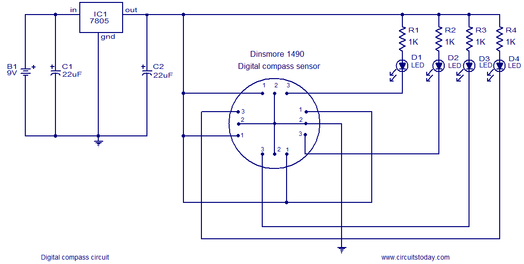
The following circuit illustrates a Digital Compass Circuit. This circuit is based on the 7805 IC. Features include a simple and accurate electronic compass. The Digital Compass Circuit utilizes the 7805 voltage regulator to provide a stable 5V supply necessary...
The digital navigation PC board may be configured for a number of navigation functions. It may be made into a simple visual digital compass, or a microcontroller based compass. The microcontroller based compass can be used for mobile robotics...
A 1999 Pontiac Montana has an information console that displays temperature, MPG, compass, and other data. This console experienced intermittent failures before completely ceasing to function. Concurrently, the radio display also malfunctioned, though the radio itself remained operational. The...