
1490 Digital Compass
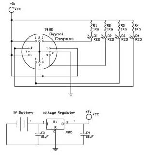
This circuit operates as a basic digital compass utilizing a sensor that detects magnetic fields and translates them into directional indicators represented by LEDs. The design leverages a 7805 voltage regulator to ensure stable operation, allowing the circuit to function effectively across a range of supply voltages. The use of micro-miniature red LEDs minimizes power consumption, making the circuit suitable for battery-powered applications. Current limiting resistors are incorporated to protect the LEDs from excessive current, ensuring longevity and reliability in performance.
The dampening mechanism within the sensor is crucial for providing stable readings, mimicking the behavior of traditional liquid-filled compasses. This feature is particularly important in dynamic environments where rapid movements could otherwise result in erratic readings. The inclusion of hysteresis further enhances the reliability of the compass by reducing the likelihood of false readings when the sensor is near a directional change.
The calibration process outlined ensures that users can easily align the digital compass with a standard magnetic compass, allowing for accurate navigation. The flexibility in choosing which LED represents north provides versatility in application, accommodating various user preferences.
In summary, this circuit exemplifies a straightforward yet effective approach to creating a digital compass, integrating essential components and features that enhance its functionality and user experience.The first test circuit (see figure 5) is about the simplest circuit that can be designed around the device. The sensor is drawn in the schematic as if you are looking through the top of the sensor to the 12 leads below.
The circuit uses four LED`s for display. Each cardinal position on the compass lights one LED. The intermediate directions light two LED`s as shown in figure 6. Notice that all the number 2 ground leads are tied together. As are the number 1 leads connected to +5 volts Vcc. The sensor will operate supply voltages from 5 to 18 volts. I used a 7805 to regulate the 9V battery to a constant 5 volts. The LED`s used in the circuit are red micro-miniature type that operate using little current. The 1K resistors limit the current flowing through the LED`s to about 5 mA. The sensor is dampened to approximate the speed of a liquid filled compass. The dampening prevents over swinging the direction. In addition the built in hysteresis prevents flutter when near a switching direction. The 1490 device is sensitive to tilt. Any tilt greater than 12 degrees will create directional errors. Figure 6, shows the minimum components of figure 5 mounted and soldered to the pc board, figure 7. Q1 is a 7805-voltage regulator. R1 through R4 are 1/8 watt 1K resistors. Four sub-miniature LED`s are soldered into the B0 through B4 positions, with the positive lead of the LED orientated on the right side with the board as shown in figure 4. Capacitors C3 and C4 are 22 uF capacitors. 9V battery cap is wired into the Vin positions, and finally a switch is wired on to the pcb in the lower left hand corner.
When I first assembled this circuit onto the board it did not function properly. The compass did not respond, as it should. I tracked the problem to the switch that is in close proximity to the compass see figure 9. The switch casing is made of a ferrous material that was disrupting the compass function. When I removed the switch and replaced it with another without any ferrous metal, the circuit responded properly. To calibrate the compass you will need to use a standard magnetic compass. Find north with the standard compass. Rotate the prototype assembly so that just one LED is lit. Use that lit LED as north. If the wiring of the sensor matches the schematic the other 3 arrays will automatically fall in proper sequence.
I used the LED furthest away from the sensor for north. The digital compass does not have a definitive magnetic north reading (position). You can make magnetic north any one of the LED readings shown below. Turning the compass in a clockwise direction will cause the LEDs to light, following the sequence shown in the table 1. In the table I chose North to be 0001, but you may make North any one of the lighted sequences, and start from there.
🔗 External reference
Related Circuits
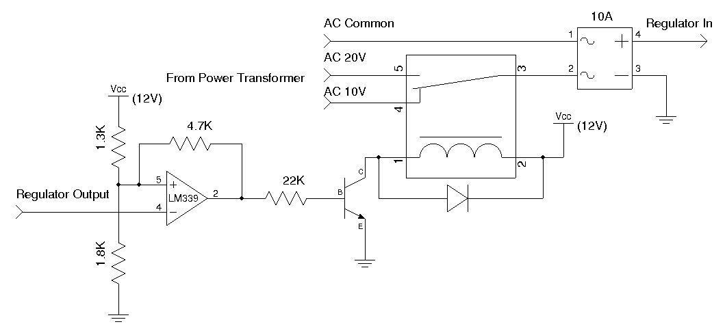
A used 250VA power transformer has been removed from equipment recently. The transformer features a dual 10V AC output along with several auxiliary voltage outputs. The 10V winding is rated for 10A, making it suitable for a high current...
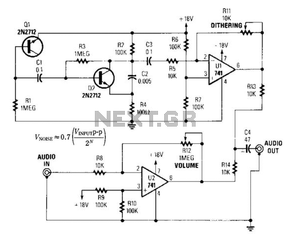
By introducing a small amount of noise to a signal intended for digitization (approximately 0.7 bits), where n represents the number of bits, for instance, an 8-bit signal with a peak-to-peak voltage of 2 V would result in a...
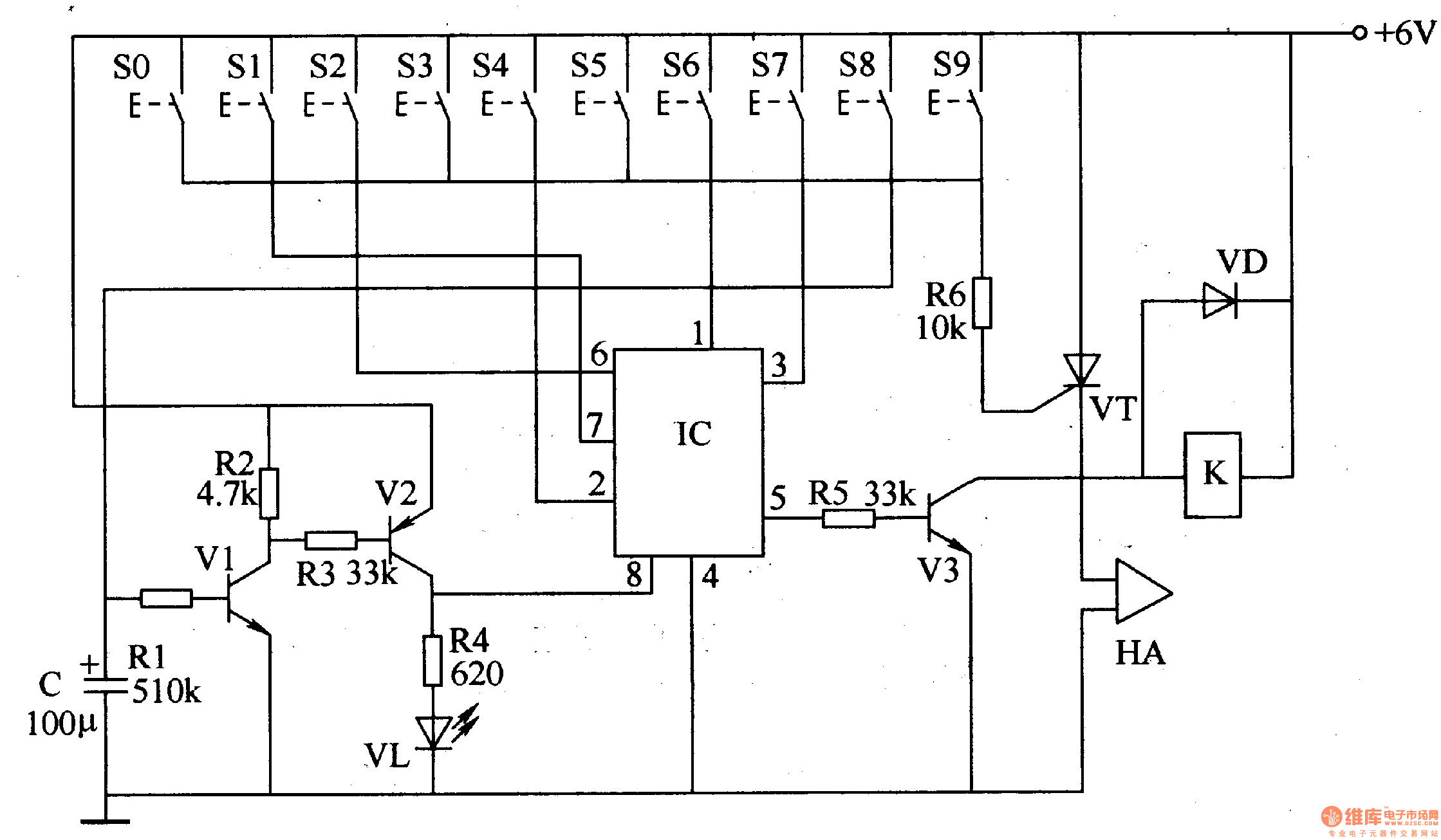
The digital lock circuit consists of a timing trigger circuit, a trick lock circuit, a sound and alarm circuit, and a control implementation circuit, as illustrated in Figure 3-101. The timing trigger circuit is made up of transistors V1...
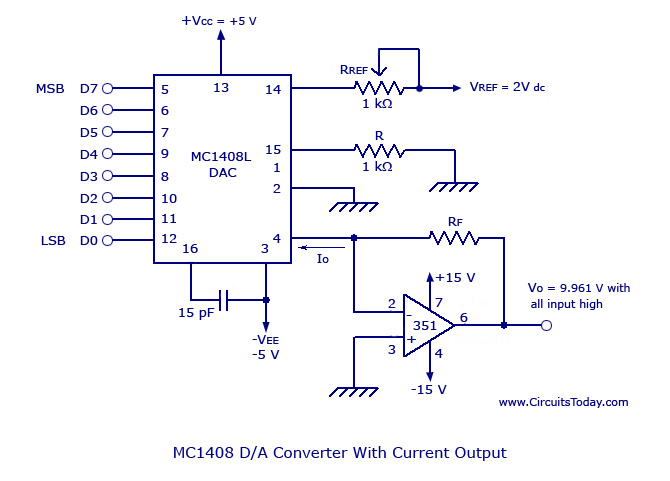
Monolithic/Hybrid Digital to Analog Converters using MC 1408 IC, SE/NE 5018, Specifications and Applications. Monolithic and hybrid digital-to-analog converters (DACs) are integral components in various electronic systems, facilitating the conversion of digital signals into corresponding analog voltages or currents. The...
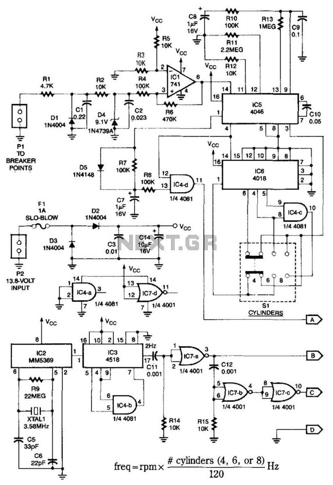
This system is compatible with 4-, 6-, or 8-cylinder automobiles. The timebase generated by IC5 functions as an oscillator that drives counter IC6, which divides the frequency by 6, 4, or 3 for 4-, 6-, or 8-cylinder engines, respectively....

This circuit provides a visual 9-second delay using a 7-segment digital readout LED. When the switch is closed, the CD4010 up/down counter is preset to 9, and the 555 timer is disabled with the output held high. The circuit utilizes...
Warning: include(partials/cookie-banner.php): Failed to open stream: Permission denied in /var/www/html/nextgr/view-circuit.php on line 713
Warning: include(): Failed opening 'partials/cookie-banner.php' for inclusion (include_path='.:/usr/share/php') in /var/www/html/nextgr/view-circuit.php on line 713