
Digital Compass for PC

The digital navigation PC board serves as a versatile platform for various navigation applications, primarily utilizing the 1490 digital compass sensor from Robson Company. This solid-state Hall effect sensor is adept at detecting the Earth's magnetic field, making it suitable for both simple visual compasses and more complex microcontroller-based systems.
In operation, the sensor can accurately indicate the four cardinal directions (N, S, E, W) and the intermediate directions (NE, NW, SE, SW) when the board is rotated. This capability is enhanced by a dampening mechanism that mimics the response of a traditional liquid-filled compass, reducing overshooting and providing stable readings. The built-in hysteresis feature further stabilizes output by preventing fluctuations when the sensor is near a directional threshold.
The 1490 sensor's design includes a sensitivity to tilt, which is a critical consideration in applications where the device may not be perfectly level. Any tilt exceeding 12 degrees can introduce significant directional inaccuracies, thus the installation and orientation of the board must be carefully managed.
The sensor's lead configuration consists of 12 pins organized into four groups of three. The first group of leads (labeled 1) is connected to a power supply of +5V (Vcc), while the second group (labeled 2) is grounded. The third group (labeled 3) serves as the output leads, functioning similarly to an open collector output of an NPN transistor. Each output can handle a continuous current of 20 mA, with a maximum intermittent current of 25 mA, allowing for reliable interfacing with microcontrollers or other processing units.
This configuration makes the digital navigation PC board an effective tool for mobile robotics, PC-based compass applications, and other navigation functions, providing both flexibility and precision in directional sensing.The digital navigation PC board may be configured for a number of navigation functions, see figure 1. It may be made into a simple visual digital compass, or a microcontroller based compass. The microcontroller based compass can be used for mobile robotics or a PC based compass. The sensor used on the PC Board is the 1490 digital compass manufactured by Robson Company, see figure 2.
This sensor is a solid-state Hall effect device. It is sensitive enough to detect the Earth's weak magnetic field. When rotated it can display the position of the four cardinal points on a compass, North (N), South (S), East (E) and West (W). As well as the intermediate directions: North East (NE), North West (NW), South East (SE), and South West (SW), see figure 3.
The sensor is dampened to approximate the speed of a liquid filled compass. The dampening prevents over swinging the direction. In addition the built in hysteresis prevents flutter when near a switching direction. The 1490 device is sensitive to tilt. Any tilt greater than 12 degrees will create directional errors. The bottom of the device has 12 leads arranged in four groups of three leads. Looking at the device from the top each group of leads are labeled 1, 2 and 3. The leads labeled 1 are connected to Vcc (+5V). Leads numbered 2 are connected to ground. And the leads labeled 3 are our output leads. The output leads of the device are equivalent to an open collector of an NPN transistor, see figure 4. Each output is capable of sinking 20 mA continuously or up to 25 mA intermittently. 🔗 External reference
Related Circuits
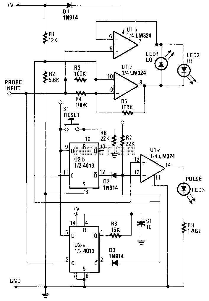
The probe operates using the power supply from the circuit under test (CUT). The input at the probe tip is divided into two pathways. One pathway directs the signal to the clock inputs of U2a and U2b. The other...

The experimenter's pot is a solid state potentiometer using Dallas semiconductor's DS1869 and National's LM78L05, two electrolytic capacitors, two small push button switches, and two optional Molex connectors. This project is very useful, especially in finding the right value...

This Project Digital Calendar using Microcontroller is an advanced digital calendar, which displays the Date, Day, Month over the LED display. It has an 8 bit Microcontroller which runs on the Program embedded on its ROM. Separate LEDs are...
A highly accurate digital thermometer utilizing an LM35 probe with a resolution of 0.1 degrees Celsius. The circuit includes two adjustable components. The first, R5, is used to calibrate the display to zero. To perform this calibration, the end...
Normally, an analog-to-digital converter (ADC) requires interfacing through a chip to convert analog signals into digital format. This necessitates both hardware and software, resulting in increased complexity and overall cost. The circuit presented here is configured around the ADC...

A digital integrated circuit simplifies the response process significantly. The diagram illustrates a circuit comprising four responder groups. The digital integrated circuit described serves as a crucial component in various electronic systems, primarily focusing on enhancing response efficiency. It comprises...