
Complementary symmetry FET operating principle
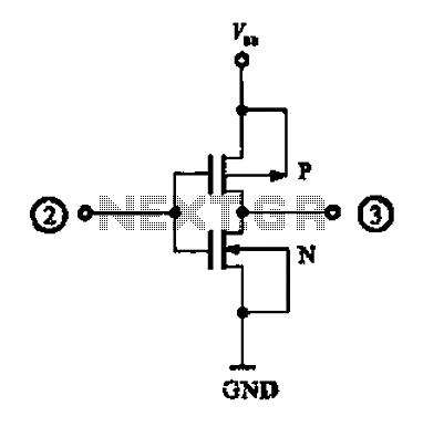
The described circuit utilizes complementary MOSFETs to create a basic inverter configuration, leveraging the properties of both N-channel and P-channel devices for efficient signal inversion. In this setup, the N-channel MOSFET is typically connected to ground, while the P-channel MOSFET is connected to the positive supply voltage. The input signal is applied to the gates of both MOSFETs.
When the input signal transitions to a high state (logical 1), the N-channel MOSFET turns on, allowing current to flow from the drain to the source, effectively pulling the output to a low state (logical 0). This is due to the fact that the N-channel device conducts when a sufficient positive voltage is applied to its gate relative to its source. At the same time, the P-channel MOSFET turns off since its gate-source voltage becomes negative, preventing current flow from the source to the drain.
Conversely, when the input signal is low (logical 0), the N-channel MOSFET turns off, and the P-channel MOSFET turns on. This configuration allows current to flow from the positive supply through the P-channel MOSFET to the output, raising the output voltage to a high state (logical 1). The complementary nature of this circuit ensures that only one of the MOSFETs is conducting at any given time, which minimizes power consumption and heat generation.
This complementary symmetry circuit is widely used in digital logic applications and can be found in various integrated circuits, including microcontrollers and digital signal processors. The CMOS technology provides high noise immunity and low static power consumption, making it the preferred choice for modern electronic devices. Proper biasing and sizing of the MOSFETs are essential for achieving optimal performance and ensuring that the switching characteristics meet the required specifications for speed and power efficiency.An N-channel MOSFET and P-channel points, with two complementary symmetry circuit composed of CMOS complementary output short circuit, as shown in the schematic for it. When th e input terminal is high (the number when lt) input, N-channel field effect transistor is turned on, pin output low level (digital o ) {When pin input low (digital o ), P-channel field effect transistor is turned on the output high (the number 1 ).
Related Circuits
This circuit can be directly connected to CD players, tuners, and tape recorders. It requires the addition of a 10K logarithmic potentiometer (dual gang for stereo) and a switch to accommodate various sources. Proper grounding is crucial to eliminate...
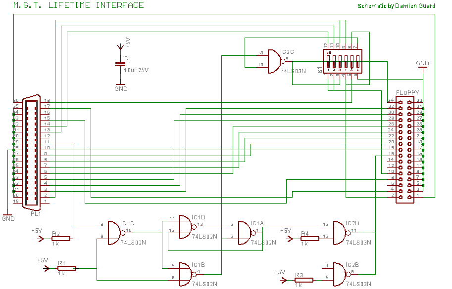
The Lifetime Drive, later renamed the Universal Drive due to concerns regarding implied warranties, was manufactured by Miles Gordon Technology (MGT) in April 1989. This floppy drive was designed to connect to most popular computers of that era. MGT...
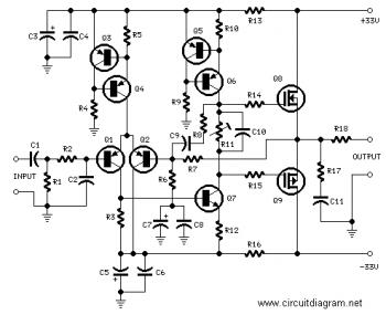
This simple power MOSFET audio amplifier circuit utilizes a TL071C operational amplifier and two MOSFETs (IRF9530 and IRF530), capable of delivering up to 45 Watts to an 8-ohm speaker. The schematic is based on a Siliconix application and incorporates...
Can be directly connected to CD players, tuners and tape recorders. Simply add a 10K Log potentiometer (dual gang for stereo) and a switch to cope with the various sources you need. A correct grounding is very important to...
The FET amplifier is designed for enthusiasts who prefer tube sound but cannot utilize traditional tube amplifiers. It exhibits output characteristics similar to bipolar FET tube amplifiers, featuring good frequency response and sound quality comparable to tube amplifiers. Coupling...
A JFET-bipolar cascode circuit is designed to deliver complete video output for driving the cathode of a CRT. The configuration offers an approximate gain of 90. The cascode arrangement mitigates issues related to the Miller capacitance of the JFET...