
Compound Op Amp Vco Driver
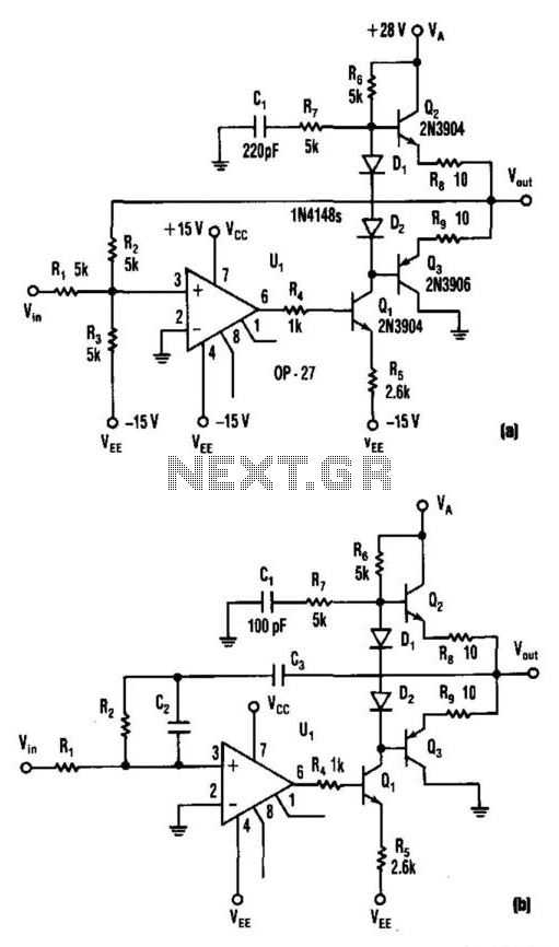
The described circuit is designed to generate an adjustable output voltage ranging from 5 V to 25 V, utilizing a standard dual power supply of ±15 V. The primary function of this circuit is to interface with a voltage-controlled oscillator (VCO), making it suitable for applications in frequency modulation and signal processing.
The components R7 and C1 are integral to the circuit's stability, providing frequency compensation to ensure that the amplifier operates effectively across its intended frequency range. This compensation helps mitigate potential oscillations or instability that could arise from the feedback loop.
Transistors Q1, Q2, and Q3 are configured as an inverting amplifier, achieving a voltage gain of two. This configuration allows the circuit to amplify the input signal while inverting its phase. The gain is determined by the values of the resistors in the feedback loop, with R2 playing a crucial role in establishing the negative feedback necessary for stable operation. The feedback mechanism ensures that the output voltage remains proportional to the input voltage, thus maintaining linearity.
The circuit's ability to function as an active load-log filter is significant for applications requiring precise signal conditioning. By employing this configuration, the circuit can filter out unwanted frequency components while allowing the desired signal to pass through, making it an effective tool for signal processing tasks.
In summary, this circuit not only provides a variable output voltage suitable for driving a VCO but also incorporates features that enhance its stability and performance in various electronic applications. Its design allows for efficient signal amplification and filtering, making it a versatile component in many electronic systems. This circuit produces 5- to 25-V output to drive a VCO from a standard ± 15-V supply system. R7 and CI supply fr equency compensation. Ql through Q3 form an inverting amplifier with a gain of two. Negative feedback through R2 closes the loop. This circuit can act as a an active load-log filter and directly drive a voltage-controlled oscillator. 🔗 External reference
Related Circuits

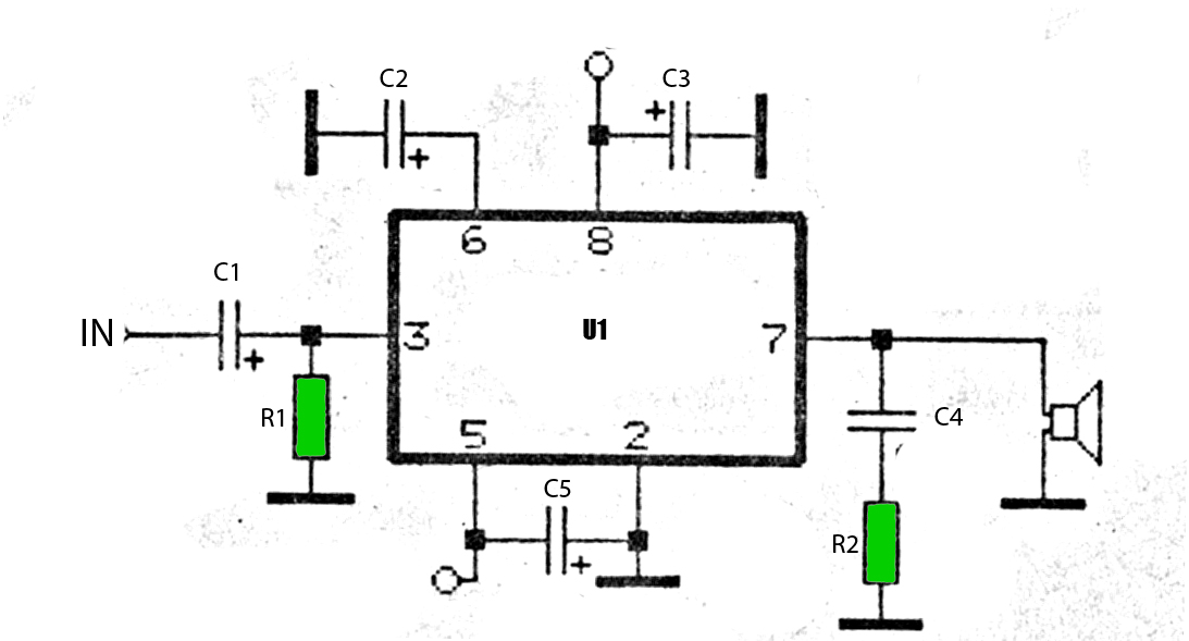
This is a stereo audio amplifier designed for automotive applications. The circuit utilizes a single integrated circuit, the TDA1553, along with several external components. This IC is responsible for managing the stereo audio system in a vehicle. The TDA1553CQ...
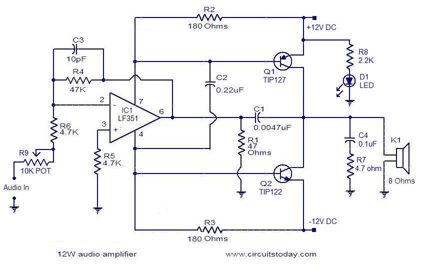
The circuit presented is a simple audio amplifier capable of delivering 12W to an 8 Ohm speaker. The operational amplifier IC TL081 serves as the preamplifier in this design. Alternatively, any operational amplifier with compatible power supply ratings can...
The car power amplifier utilizes the SI1050GL integrated circuit (IC) as the primary amplification component. It delivers an output power of 50 Watts at an 8-ohm mono impedance. The amplifier operates with a DC voltage of up to 25...
The shunt-feedback configuration facilitates the straightforward integration of frequency-dependent networks, enabling a functional and discreet switchable tilt control (optional). When SW1 is in the first position, a gentle shelving bass boost and treble attenuation occur. The central position of...
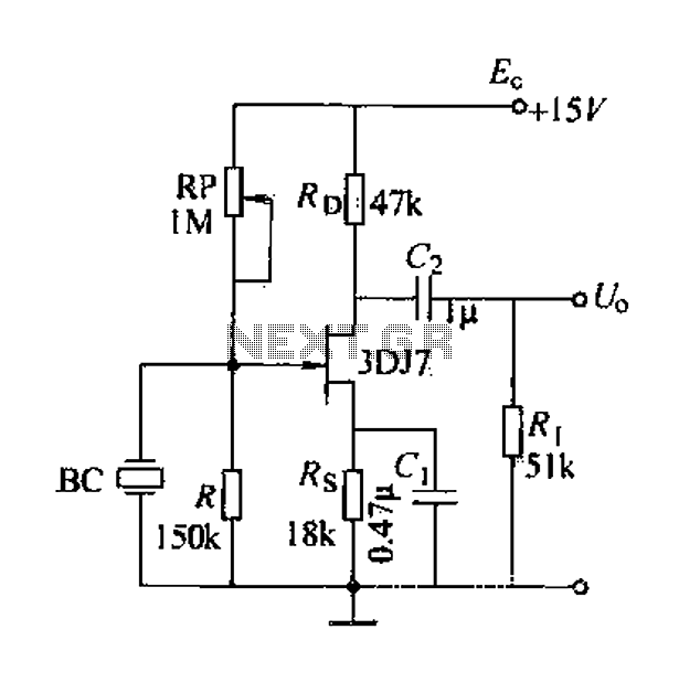
A field effect transistor (FET) voice amplifier has a low input impedance, approximately 1 kΩ, requiring the signal source to provide a constant current signal for operation. Unlike bipolar transistors, FETs are voltage-controlled devices that draw minimal current at...
The BQ2000 is a programmable, monolithic integrated circuit designed for fast-charge management of nickel cadmium (NiCd), nickel metal-hydride (NiMH), or lithium-ion (Li-Ion) batteries in single or multi-chemistry applications. The BQ2000 detects the battery chemistry and employs optimal charging and...