
Compressor For Electret Microphone

The FM Remote Control Receiver circuit is designed for efficient operation in intercom and P.A. applications. The use of the CA3080 OTA allows for precise control of the gain, while the TS924IN quad op-amp ensures optimal signal processing. The adjustments to component values, such as R15 and R6, demonstrate the importance of fine-tuning in achieving desired performance characteristics, particularly in terms of gain and frequency response. The feedback mechanism involving D1/C3 and IC2b is crucial for maintaining stability and preventing distortion in the output signal. The design considerations for power supply and component ratings reflect a comprehensive understanding of the circuit's operational limits, ensuring reliable performance across various conditions. The recommendation for battery use emphasizes the circuit's versatility and adaptability to different power sources, making it suitable for portable applications. Overall, this circuit exemplifies a well-engineered solution for audio amplification and signal processing in remote communication systems.The FM Remote Control Receiver` (available on this website in Infra-red circuits section) has a connector where an analogue output is made available. To make a simple intercom or P. A. system the associated transmitter needs a microphone pre-amplifier that outputs a signal at the correct level.
And that is exactly the function of this circuit. Actu ally, this design is adapted from a circuit published last year (AM Modulator for Intercom`). A few things have been changed so that it can work with the 5 V supply from the transmitter module. The OTA (IC1) used here is the single version (CA3080), which has slightly different characteristics from the dual CA3280. The quad opamp is the same rail-to-rail TS924IN, made by ST. The turnover frequency of the ¬lter (3rd order 1 dB Chebyshev) has been increased slightly to improve the intelligibility of speech and is now about 5.
5 kHz. The ¬lter now ampli ¬es the signal by a factor of 10. In practice it is possible that due to various tolerances and the fact that the opamp is not perfect, the ¬lter characteristic shows some deviation from that required. In our prototype it was necessary to change R15 into 2k7 to straighten the response curve. The DC current variation at the output of the OTA and the resulting offset variation at the output of current/voltage converter IC2d is such that the gain of IC2d has to be substantially smaller than in the old` design.
Otherwise the output could easily rise to the supply voltage at low signal levels. The value of R6 has therefore been made smaller by a factor of 10. This has reduced the gain of the circuit by 20 dB, which is compensated for in the ¬lter. The amplitude of the signal from IC2d is fed back as a control current to the OTA by peak recti ¬er D1/C3 and inverting ampli ¬er IC2b. R7 limits the loading on IC2d. P1 can be used to adjust the amplifier between a fixed gain and maximum compression. Figure A shows clearly what effect the circuit has. 0 dBr corresponds to 100 mV. The maximum gain, with P1 set to maximum compression, is about 48 dB (250 ) for small signals. The minimum gain is about 20 dB (10 ). The OTA is then slightly overdriven and the distortion becomes several percent! With a ¬xed gain selected (P1 shorted) the gain is about 42 dB (125 G—). The middle curve was measured with P1 in its central position. The curve drawn for a ¬xed gain (the straight line) doesn`t ¬nish at the edge of the graph because the end of the line corresponds to the maximum possible output level, which is 25 dBr (‰ 1.
76 V or 5 / 2 2). Figure B shows the frequency response. The low turnover frequency is mainly determined by C8 (and to a lesser extent by C1) and is about 120 Hz. The current consumption is about 7 mA When the circuit is battery powered we recommend the use of three AA cells, because the circuit still works perfectly at 4.
5 V. If you want to use a higher supply voltage (maximum 12 V for the de TS924IN and 30 V for the CA3080, but you should also think of the voltage across the electret microphone!) you have to keep in mind that the maximum current through R9 (which is IABC) is only 2 mA. When we consider a maximum chosen current of 1 mA and the maximum output voltage of IC2b (half the supply voltage, which is 2.
5 V), then the value of R9 should be (2. 5 0. 7) V / 1 mA = 1. 8 k. The value of 0. 7 V corresponds to the potential between pin 5 and earth. For a larger safety margin R9 is calculated with the full supply voltage and a current of 2 mA: (5 0. 7) V / 2 mA = 2k2 (rounded upwards). Of course the regulation will then be different (a little less gain). This circuit and the transmitter module can therefore be fed from the same 5 V supply. Because the transmitter requires a DC offset at its input, a resistor is connected to +5 V via a jumper, which biases the output to half the supply voltage.
With the jumper open R17 functions as a load resistor when the output is n 🔗 External reference
Related Circuits
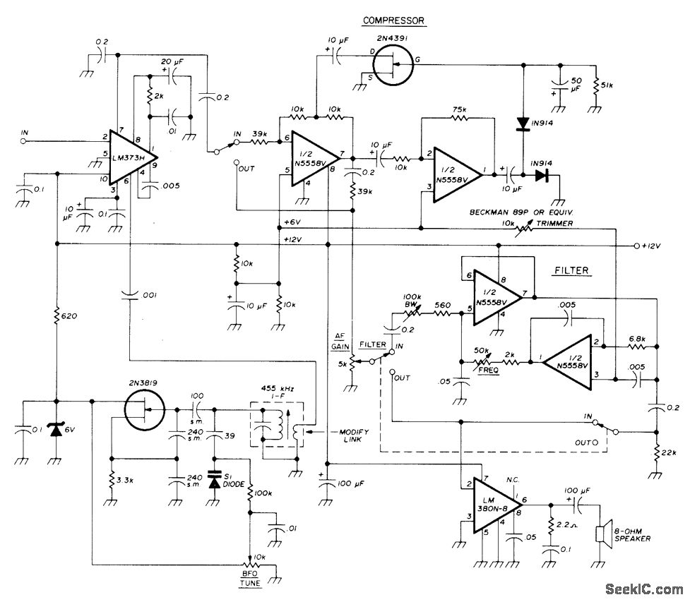
A combination of an intermediate frequency (IF) amplifier, audio compressor, tunable audio filter, and audio output system operates from a single supply. The compressor and filter each utilize N5558V dual operational amplifiers or equivalent units. The tuning range of...
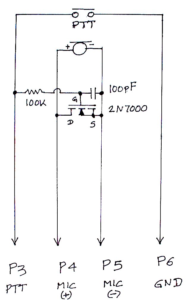
The TS-440S, similar to several other radios, does not mute the microphone when utilizing the rear audio connector for digital modes. Consequently, unless the microphone is unplugged each time digital modes are used, background noise from the shack can...
In personal electronics and computer audio systems, the SSM2167 is a complete and flexible solution for conditioning microphone inputs. It is also very good for various applications. The SSM2167 is an integrated circuit specifically designed for microphone preamplification and audio...
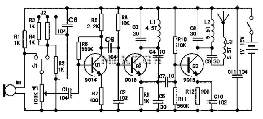
The design of an FM radio transmission frequency band enables compatibility with any FM radio receiver, allowing the high-frequency signal to be transmitted and restored from an audio signal. This technology serves various applications. Applications of a wireless microphone...
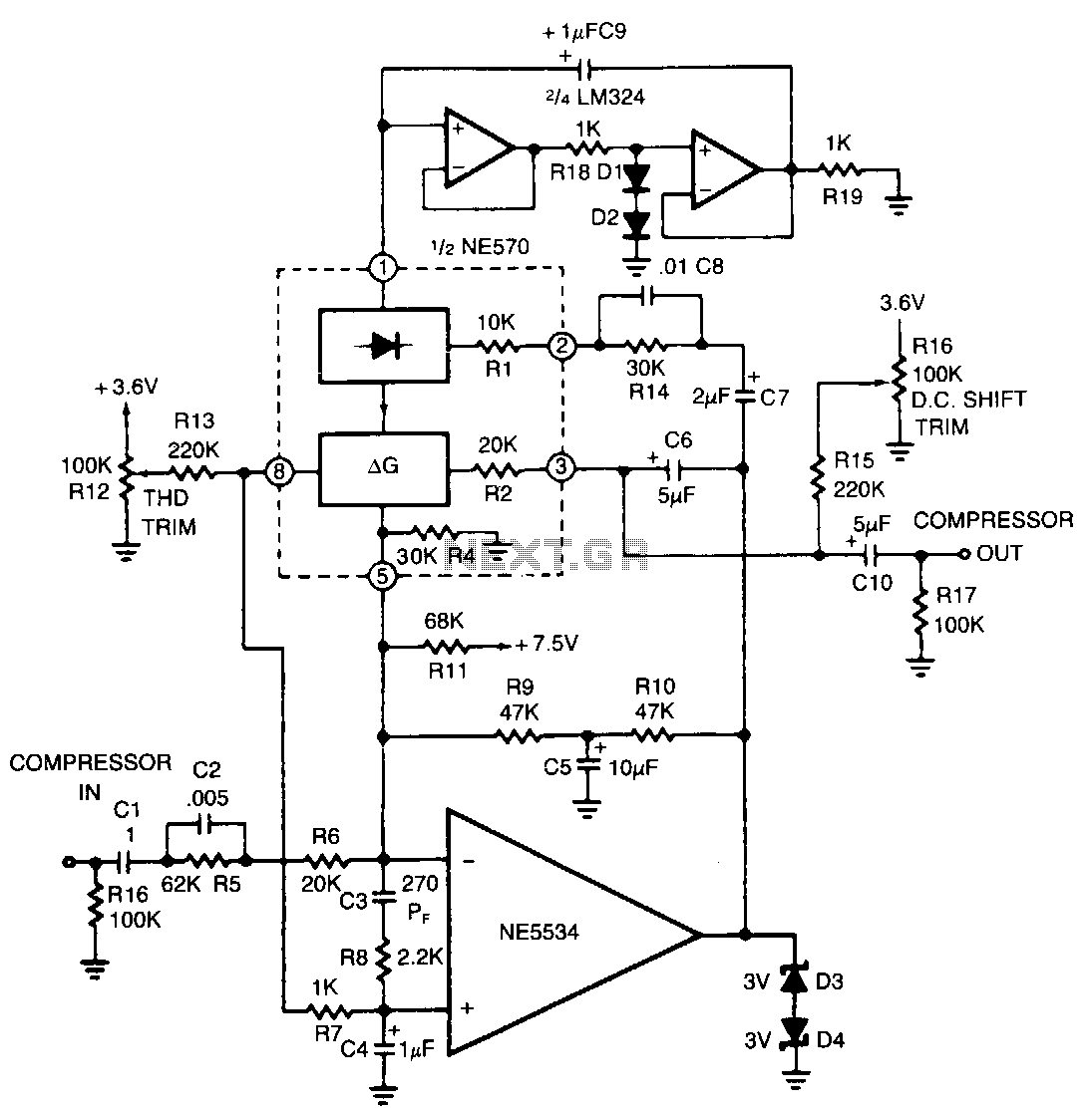
The compressor includes a high-frequency pre-emphasis circuit (C2, R5, CS, R14) that addresses this issue. A corresponding de-emphasis circuit on the expander is necessary. More sophisticated designs may allow for variable pre-emphasis. The compressor's high-frequency pre-emphasis circuit is crucial for...
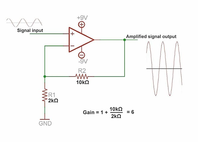
An amplifier is a device that increases the voltage in a circuit. The simplest type is an operational amplifier, and this video will demonstrate how these devices function and how to implement them in electronic applications. As an example,...