
Computer AC power source monitoring circuit
The circuit design incorporates a current transformer that senses the alternating current (AC) load typical in computer systems. This transformer is critical for monitoring the current flow in the power line, allowing for real-time status assessment. The LM393 comparator serves as a key component in this circuit, providing a means to compare voltage levels and generate an output based on the comparison results.
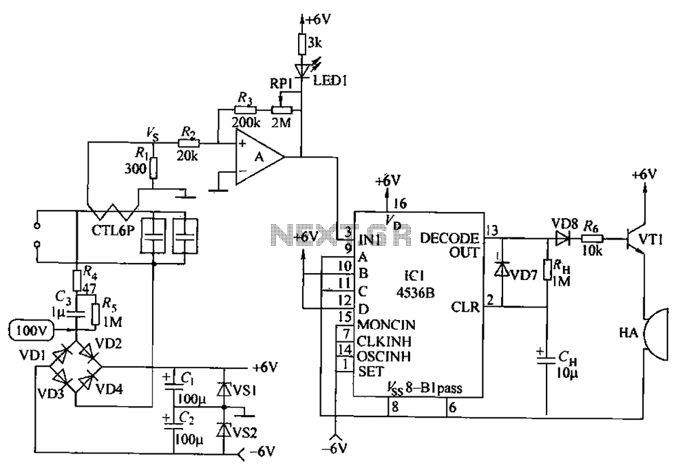
Upon powering the circuit, IC1 is responsible for setting the alarm time interval, which is crucial for the operation of the system. The circuit is designed to accept input signals labeled A, B, C, and D. The configuration of these inputs determines the operational state of the circuit. Specifically, when inputs B and D are high and A and C are low, the circuit is prepared to process the input time.
The circuit also features a frequency division mechanism that divides the input power frequency by two. This is particularly relevant when considering standard power frequencies of 50Hz or 60Hz, which are common in electrical systems worldwide. The timing calculations indicate that an output signal will be generated after approximately 87 minutes for a 50Hz input frequency and 73 minutes for a 60Hz input frequency.
The output from the decoder (DECODE() UT) becomes high at the end of the designated time interval, triggering the transistor VT1. This action activates the buzzer (HA), producing an audible alert. The duration of the buzzer sound is controlled by the resistor RI-I and capacitor CH, allowing for customization of the alarm duration based on user requirements or specific application needs. This comprehensive design facilitates effective monitoring and alerting in environments with significant power loads, enhancing operational safety and reliability. Circuit principle: computers AC power load is large, the use of the current transformer current sensing. It can be used to detect whether a current power line, determine its st atus. Schmitt is LM393 comparator circuit (A), after the power is turned on, set the alarm time interval by IC1 completed. When the input time (A, B, C, D) ended input binary code, 1C1 time interval can be set. B, D is set to the high level, A, and C is set to a low level. 1C1 input power frequency 1/2 division. If the power frequency is 50Hz, after about 87min, when power frequency is 60H, after about 73min, the output of the decoder (DECODE () UT) output high, VT1 conduction, HA buzzer sound, the sound of time from RI-I, CH decision.
Related Circuits
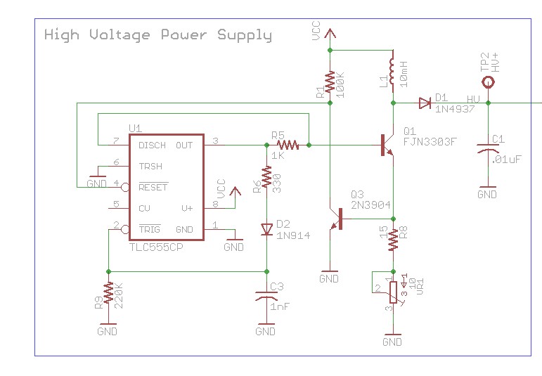
The design involves using a 555 timer as an oscillator in the high voltage power supply section. There is a query regarding the possibility of altering the design to utilize an output from a microcontroller to generate an oscillating...
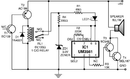
This heat detector alarm electronic project is designed using the UM3561 sound generator circuit along with several common electronic components. The heat detector circuit employs a complementary pair of transistors, consisting of an NPN and a PNP transistor, to...
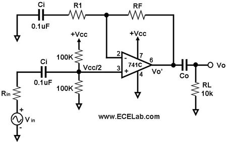
All the capacitors are present to block DC signals; however, the values of capacitance are crucial, and it is necessary to determine the value of Co. Rin denotes the source resistance, which is not an integral part of the...
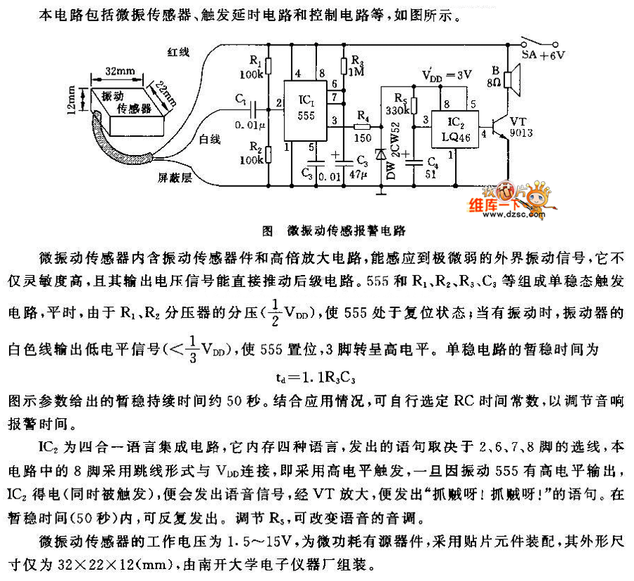
This circuit features a micro vibration sensor, a trigger delay circuit, and a control circuit, as illustrated in the accompanying figure. The micro vibration sensor comprises a vibration sensing device and a high power amplifier circuit, enabling it to...
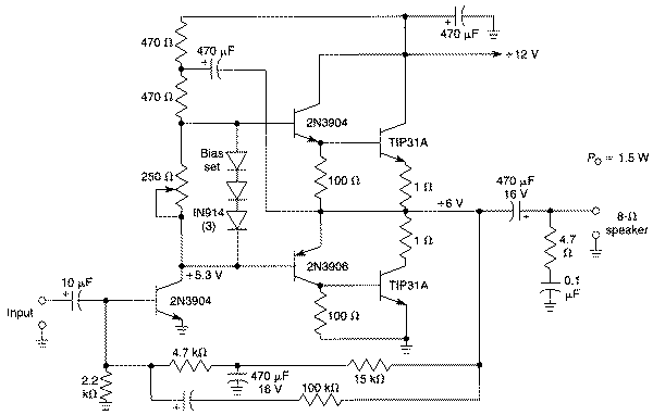
Integrated circuits (ICs) have largely replaced traditional circuits like this one; however, this circuit is still utilized where the flexibility of a discrete device design is desirable. The components are readily available, and the issue of IC obsolescence is...
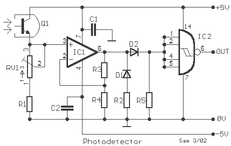
This circuit gives a low-level output when sufficient lighting is present, functioning as a light detector. It can issue a command to turn on lights when darkness falls. Its output is compatible with TTL levels, providing a low logic...