
Using microcontroller as oscillator for high voltage power suppy
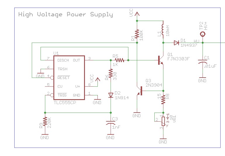
The 555 timer is a versatile integrated circuit commonly used in various applications, including oscillators, timers, and pulse generation. Its popularity in power supply designs, especially high-voltage applications, stems from its simplicity, reliability, and ability to generate precise timing intervals and waveforms. The 555 timer can operate in astable mode, producing a continuous square wave output, which is essential for driving switching devices such as transistors or MOSFETs in power supply circuits.
In considering the use of a microcontroller to generate an oscillating signal, several factors must be evaluated. Microcontrollers can produce PWM (Pulse Width Modulation) signals or other waveform outputs, which can be utilized to control power devices similarly to a 555 timer. The advantages of using a microcontroller include programmability, flexibility in waveform generation, and the ability to adapt to varying operational requirements without changing hardware.
However, the design's effectiveness would depend on the microcontroller's specifications, including its maximum output frequency, current drive capability, and the nature of the load it will control. If the microcontroller can provide a stable and sufficient oscillation frequency for the application, then the design could function properly.
The choice of the 555 timer in the original design may be due to its inherent characteristics, such as ease of implementation, minimal external component requirements, and robustness in various environmental conditions. Additionally, the 555 timer can handle higher voltage levels directly, which can be advantageous in high-voltage applications, whereas microcontrollers may require additional circuitry to interface safely with such voltages.
In conclusion, while it is feasible to replace the 555 timer with a microcontroller for generating oscillating signals, careful consideration of the design requirements and the capabilities of the microcontroller is essential to ensure reliable operation in high voltage power supply applications.Using the 555 timer as an oscillator in the high voltage power supply section. Can the design be changed to use an output from the micro-controller to generate an oscillating signal instead of the 555. The first question is that would such a design work If it works, is there a particular reason why a 555 timer is used in the design
🔗 External reference
Related Circuits
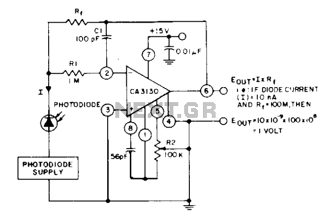
The circuit utilizes three CA3130 BiMOS operational amplifiers in an application that is sensitive to sub-picoampere input currents. It provides a ground-referenced output voltage that is proportional to the input current flowing through the photodiode. The circuit design employs three...
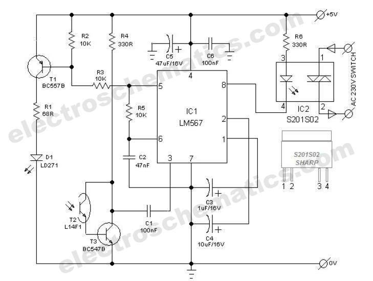
The power switch with an infrared proximity sensor is designed to detect obstructions at distances ranging from a few millimeters to several centimeters. The power switch utilizing an infrared proximity sensor operates on the principle of emitting infrared light and...
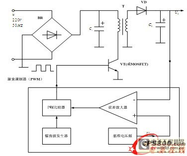
The energy conservation provided by switching power supplies has garnered significant attention due to its substantial economic benefits, leading to rapid adoption across various sectors. With the swift advancement in power technology, high-frequency operation has become a prevailing trend...
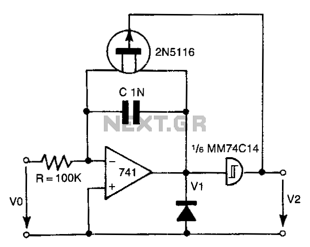
The 741 operational amplifier integrator signal is input into the Schmitt trigger of an inverter. When the signal reaches the positive-going threshold voltage, the inverter's output switches to zero. This output directly controls the FET switch. With a gate...
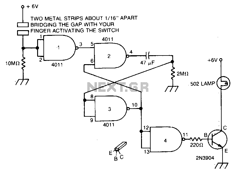
Touch the plate, and the light will turn on and remain on due to the 47 µF capacitor and the 2MΩ resistor for a duration determined by the timing resistor. The circuit described involves a touch-sensitive plate that activates a...
Switch on one unit, and everything else you need turns on automatically. This can save the tedium of turning on half a dozen different things, when one should be enough! This is another project created purely from necessity. In...