Micro vibration sensor alarming circuit diagram
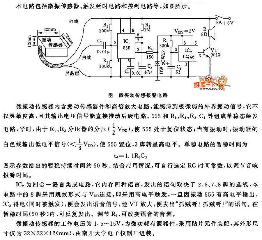
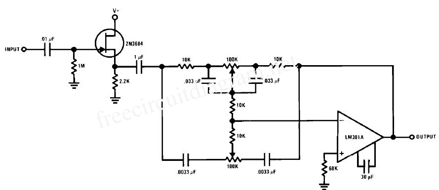
This circuit features a micro vibration sensor, a trigger delay circuit, and a control circuit, as illustrated in the accompanying figure. The micro vibration sensor comprises a vibration sensing device and a high power amplifier circuit, enabling it to detect very weak external vibration signals. It exhibits high sensitivity, and its output voltage signal can directly drive the subsequent stage of the circuit.
The circuit is designed to detect minute vibrations through the micro vibration sensor, which operates by converting mechanical vibrations into electrical signals. The sensor's high sensitivity allows it to pick up even the faintest vibrations, making it suitable for applications where precise monitoring is essential. The integrated high power amplifier enhances the sensor's output, ensuring that the signal strength is sufficient for further processing.
The trigger delay circuit serves to manage the timing of the output signal generated by the vibration sensor. This feature is crucial in applications where immediate response to vibrations may not be necessary or could lead to false triggering. By introducing a delay, the circuit can filter out transient vibrations that may be caused by environmental noise or other non-critical disturbances.
The control circuit processes the output from the trigger delay circuit, enabling the activation of other components in the system based on the detected vibrations. This could include turning on alarms, activating motors, or interfacing with microcontrollers for further data processing. The design ensures that the entire system operates efficiently, with minimal power consumption while maintaining high responsiveness to vibration stimuli.
Overall, this circuit represents a sophisticated solution for applications requiring vibration detection and response, combining sensitivity, timing control, and effective signal processing in a compact design.This circuit includes micro vibration sensor, trigger delay circuit and control circuit, the figure is as shown. The micro vibration sensor contains vibration sensor device and high power amplifier circuit, it can induce very weak external vibration signal, it has high sensitivity, and its output voltage signal can push the backward stage circuit directly..
🔗 External reference
