
Computer Data Cable Tester

This device functions as a basic cable tester, designed to assess the integrity and functionality of computer data cables, such as Ethernet or USB. It typically consists of two main components: a transmitter and a receiver. The transmitter is connected to one end of the cable, while the receiver connects to the opposite end.
Upon activation, the transmitter sends a series of electrical signals through the cable. These signals can take the form of pulses or specific patterns, which the receiver then interprets. The device is capable of identifying several potential issues, including open circuits, short circuits, and miswired connections.
Indicators such as LEDs or a simple display may be used to convey the results of the test. For instance, a green light may indicate a successful connection, while a red light could signify a fault. This straightforward approach allows users to quickly determine whether a cable is functioning correctly, making it an invaluable tool for both professionals and hobbyists in the field of electronics.
In addition to basic testing capabilities, some advanced models may include features such as cable length measurement, signal quality analysis, and compatibility checks with various cable standards. This versatility enhances the utility of the device, allowing for more comprehensive diagnostics and maintenance of computer networks.
Overall, this cable testing device serves as an essential tool for ensuring reliable data transmission in computer systems, facilitating efficient troubleshooting and minimizing downtime.You don t need access to fancy test gear to check and fault-find computer data cables. Instead, this simple device will give a quick indication of the sta.. 🔗 External reference
Related Circuits
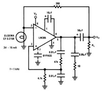
This device has a quiescent power drain of 24 milliwatts when operating from a 6 V supply, making the LM386 ideal for battery operation. According to the application hints section of the LM386 datasheet, two pins (1 and 8)...

The PACO C-25 differs from the Healthkit IT-22b in that it tests both regular and electrolytic capacitors and utilizes a 40 MHz oscillator to allow a rough measurement of capacitance through a bridge circuit. In vintage vacuum tube equipment,...

This compact circuit is designed to verify the basic functionality of an infrared remote control unit. It operates on the straightforward principle of connecting a piezo buzzer directly to an infrared (IR) receiver integrated circuit (IC). This approach is...
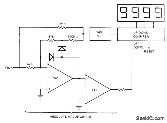
The absolute-value integrator circuit generates the effect of producing negative frequencies when the input signal is negative. It accomplishes this by allowing the counter to count up for positive voltage and count down for negative voltage. The specific types...

This circuit is designed to detect the approximate percentage of salt contained in a liquid. After careful calibration, it provides a quick, rough indication of the salt content in liquid foods for dietary purposes. The circuit utilizes the LM324...
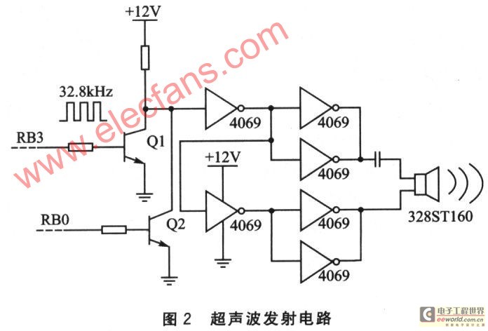
This device is based on the PIC16F628A microcontroller and utilizes a pair of independent ultrasonic transducers for both transmission and reception. It employs the Doppler effect to effectively detect whether someone enters a designated area and can control the...