
salt tester circuit

The circuit operates by measuring the DC resistance between two probes immersed in the liquid. As salt is dissolved in water, the electrical conductivity increases, leading to a decrease in resistance. The differential amplifier configuration of IC1A amplifies the voltage change corresponding to the resistance variation. The output from IC1A is fed into the inverting inputs of the comparators IC1B, IC1C, and IC1D, which are set to trigger at specific voltage levels that correspond to predetermined salt concentrations.
The reference voltages provided by D1 and D2 are crucial for ensuring accurate readings. D1 provides a lower reference of 1.6V, which is used to power the probes and calibrate the circuit. D2, with its higher reference of 3.2V, stabilizes the non-inverting inputs of the comparators, thus ensuring that the circuit remains responsive to changes in salt concentration.
The LEDs serve as visual indicators for the user. The absence of illumination indicates low salt content, while the sequential illumination of yellow, green, and red LEDs provides a clear and immediate indication of increasing salt concentration. The use of a setup trimmer (R4) allows for fine-tuning of the circuit, accommodating variations in probe sensitivity and ensuring reliable performance across different samples.
This circuit can be applied in various scenarios, including food processing, laboratory testing, and dietary monitoring, where quick and approximate measurements of salt content are required. The simplicity of the design, combined with the effectiveness of the LM324 operational amplifier, makes it a practical solution for users needing to monitor salt levels in liquids.This circuit was designed to detect the approximate percentage of salt contained in a liquid. After careful setting it can be useful to persons needing a quick, rough indication of the salt content in liquid foods for diet purposes etc. This circuit is using LM324 as main components. This is the figure of the circuit; IC1A op-amp is wired as a DC differential amplifier and its output voltage increases as the DC resistance measured across the probes decreases. In fact, fresh water has a relatively high DC resistance value that will decrease proportionally as an increasing amount of salt is added.
IC1B, IC1C and IC1D are wired as comparators and drive D5, D4 and D3 in turn, as the voltage at their inverting inputs increases. Therefore, no LED will be on when the salt content of the liquid under test is very low, yellow LED D5 will illuminate when the salt content is low, green LED D4 will illuminate if the salt content is normal and red LED D3 will illuminate if the salt content is high.
D1 and D2 are always on, as their purpose is to provide two reference voltages, thus improving circuit precision. At D2 anode a stable 3. 2V supply feeds the non-inverting inputs of the comparators by means of the reference resistor chain R8, R9 and R10.
The 1. 6V reference voltage available at D1 anode feeds the probes and the set-up trimmer R4. One of these two red LEDs may be used as a pilot light to show when the device is on. 🔗 External reference
Related Circuits
Common LED driver requirements include a wide and overlapping range of LED string voltages and input voltages. Many designers prefer to use an LED driver circuit that accommodates various battery power sources and multiple LED strings. This universal configuration...

This inverter circuit is designed to power electric razors, stroboscopes, flash tubes, and small fluorescent lamps using a 12-volt car battery. Unlike typical feedback oscillator inverters, this design features a separate oscillator from the output stage, allowing for easy...
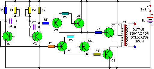
This is a simple and cost-effective inverter designed for small soldering irons (25W, 35W, etc.) to be used in the absence of mains supply. The circuit employs eight transistors along with a few resistors and capacitors. Transistors Q1 and...

The FIG potentiometer RP2 has a sliding contact that is directly connected to the antenna. The system operates such that only when potentiometers RP1 and RP2 are positioned identically, do the non-conductive transistors and rectifier bridge remain off, resulting...
Model Railroader is the world's largest magazine on model trains and model railroad layouts. It offers assistance for both beginners and advanced enthusiasts across all model railroading scales, including layout track plans, product reviews, news, and forums. Model Railroader magazine...

This is a design circuit diagram of a moderate power FM transmitter circuit. The circuit operates using two transistors. It consists of a complete circuit diagram. The operation of this circuit is explained as follows: the voice signals picked...
Warning: include(partials/cookie-banner.php): Failed to open stream: Permission denied in /var/www/html/nextgr/view-circuit.php on line 713
Warning: include(): Failed opening 'partials/cookie-banner.php' for inclusion (include_path='.:/usr/share/php') in /var/www/html/nextgr/view-circuit.php on line 713