
computer off switch schematics
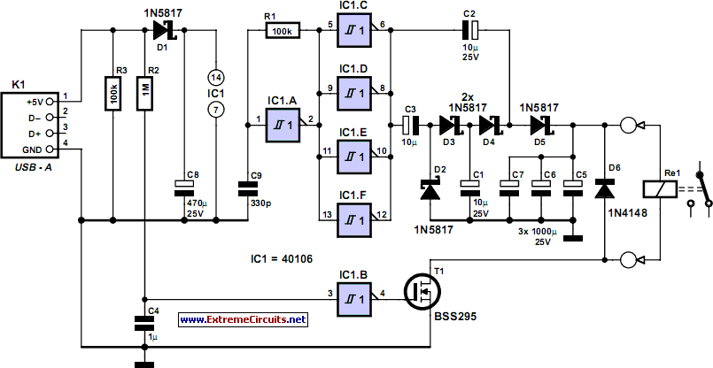
This circuit is an efficient solution for automating the shutdown process of a computer, ensuring that the device is completely powered off after use. The design incorporates safety features to prevent accidental exposure to mains voltage, which is critical in any circuit interfacing with high voltage. The use of a voltage multiplier allows the circuit to function effectively with minimal components, while the square wave oscillator provides the necessary frequency for the inverters to operate. The selection of components, such as the BSS295 transistor and the specific values of resistors and capacitors, is crucial for maintaining the desired operational parameters and ensuring reliable performance. Furthermore, the implementation of heat shrink insulation on mains connections enhances safety by preventing short circuits and accidental contact. Overall, this circuit exemplifies a practical approach to enhancing user convenience and safety in computer operation.How often does it happen that you close down Windows and then forget to turn off the computer This circuit does that automatically. After Windows is shut down there is a click` a second later and the PC is disconnected from the mains.
Surprisingly enough, this switch fits in some older computer cases. If the circuit doesn`t fit then it will have to be housed in a separate enclosure. That is why a supply voltage of 5 V was selected. This voltage can be obtained from a USB port when the circuit has to be on the outside of the PC case. It is best to solder the mains wires straight onto the switch and to insulate them with heat shrink sleeving.
C8 is charged via D1. This is how the power supply voltage for IC1 is obtained. A square wave oscillator is built around IC1a, R1 and C9, which drives inverters IC1c to f. The frequency is about 50 kHz. The four inverters in parallel power the voltage multiplier, which has a multiplication of 3, and is built from C1 to C3 and D2 to D5. This is used to charge C5 to C7 to a voltage of about 9 V. The generated voltage is clearly lower than the theoretical 3x4. 8=14. 4 V, because some voltage is lost across the PN-junctions of the diodes. C5 to C7 form the buffer that powers the coil of the switch when switching off. The capacitors charge up in about two seconds after switching on. The circuit is now ready for use. When Windows is closed down, the 5-V power supply voltage disappears. C4 is discharged via R2 and this results in a 0` at the input of inverter IC1b. The output then becomes a 1`, which causes T1 to turn on. A voltage is now applied to the coil in the mains switch and the power supply of the PC is turned off.
T1 is a type BSS295 because the resistance of the coil is only 24R. When the PC is switched on, the circuit draws a peak current of about 200 mA, after which the current consumption drops to about 300 µA. The current when switching on could be higher because this is strongly dependent on the characteristics of the 5-V power supply and the supply rails in the PC.
There isn`t much to say about the construction of the circuit itself. The only things to take care with are the mains wires to the switch. The mains voltage may not appear at the connections to the coil. That is why there has to be a distance of at least 6 mm between the conductors that are connected to the mains and the conductors that are connected to the low-voltage part of the circuit. 🔗 External reference
Related Circuits
The 2N388A transistors are inexpensive (approximately 18 cents when purchased in lots of five or more). The 2N5088 transistors are readily available from Mouser. Other components can typically be sourced from Radio Shack or local stores. To convert to...
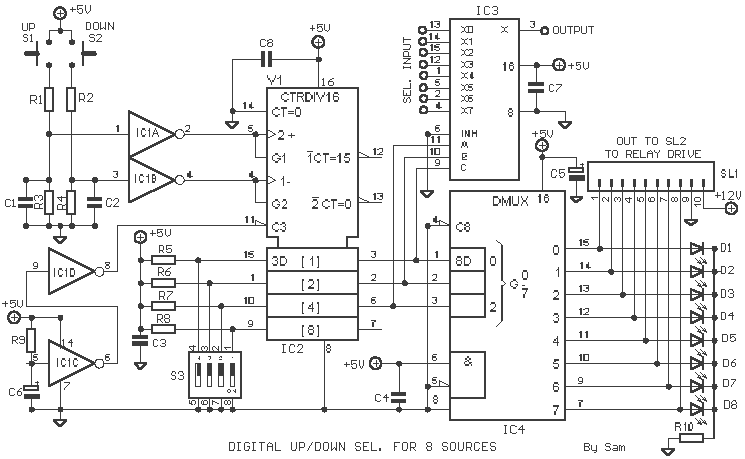
As with the Electronic sel. 8 we also have here a circuit with a choice of 8 different sources. The difference is that only two of the switches are used and the movement of commands is Up-Down in series....
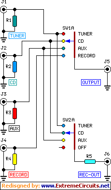
This module is an essential addition to the Modular Preamplifier Control Center when more than two sources need to be connected to the preamplifier chain. Four high-level inputs can be selected using SW1 and routed to the output. The...
This week, there was a Southern theme in anticipation of Spring Break, leading to the decision to build a LassoBot. This robot throws a lasso in a circular motion until it captures an object in its path. Once an...

This project couldn't be any simpler if it tried. Using the PC's internal 12V supply to operate a relay, it is 100% reliable. If the PC is on, the peripherals are on and vice versa - it can't be...

The following diagram illustrates a 50W offline switching power supply circuit design. This circuit is powered by a MOSFET, specifically the BUZ80A/IXTP4N8 for a 220V AC voltage input and the GE IRF823 for a 110V AC voltage input. The...
Warning: include(partials/cookie-banner.php): Failed to open stream: Permission denied in /var/www/html/nextgr/view-circuit.php on line 713
Warning: include(): Failed opening 'partials/cookie-banner.php' for inclusion (include_path='.:/usr/share/php') in /var/www/html/nextgr/view-circuit.php on line 713