
pedal schematics
The schematic incorporates the 2N388A and 2N5088 transistors as the primary amplification components, ensuring a robust gain structure. The orientation of the 47uF electrolytic capacitor is crucial for functionality when converting to PNP configuration; this alteration affects the biasing of the transistors and overall circuit operation. The input capacitor plays a significant role in shaping the tonal characteristics, with a recommended range of 2uF to 10uF, allowing for a broader input signal response that enhances the fuzz effect. The output capacitor's role, while less critical, still influences the tonal balance; thus, experimenting with values such as 1uF and 0.05uF can yield desirable results without compromising the integrity of the original signal.
Utilizing trimpots in the circuit design provides the user with the ability to fine-tune the distortion characteristics, allowing for a personalized sound profile. The high-end roll-off capacitor (C) can be adjusted to various values to explore different frequency responses, making socketing this component advantageous for experimentation. The inclusion of a 50K potentiometer prior to the input capacitor can improve the circuit's adaptability, as illustrated in the Fuzz Face technology references.
For those looking to modify the output level, the suggested alteration of the 1K resistor at Q2's collector to a 47K resistor, in conjunction with adjusting the trimpot, can effectively manage the output signal. This modification allows for a more controlled and subdued output, which can be particularly beneficial in certain musical contexts.
The Insanity Box and The Rocket circuits exemplify the versatility and potential of transistor-based fuzz pedals. The Insanity Box is characterized by its aggressive sound, while The Rocket offers a smooth and rich tonal palette, making it suitable for various musical styles. The availability of PCBs for these designs facilitates accessibility for builders, especially beginners, allowing them to create professional-grade pedals with relative ease. These designs reflect a blend of creativity and technical skill, showcasing the possibilities within analog pedal construction.Try the 2N388A transistors as they are dirt cheap (18 cents when bought in lots of 5 or more I think). The 2N5088s can be readily found through Mouser. The rest is pretty much Radio Shack or your local store. Convert to PNP transistors by changing the orientation of the lone 47uF electrolytic and reversing the battery polarity.
(The battery AND 47uF cap POSITIVE to ground). Mods: The input cap is critical; for classic fat fuzz tones use 2. 2uF to 10uF to larger! (you may consider socketing it - I did) The output cap is less critical; I have found that. 1uF is fine for me. The. 05uF that I use I have found to be very good because it changes the frequency response of my guitar the least. I have around the same bass as when the unit is bypassed. The trimpots allow you to really tune in the sound. Many shades of distortion will come out as you fool around and turn them. C is a high end rolloff cap, you can put. 001 to. 01 to larger values and hear what it does (socket this cap). You can also put the usual 50K pot at the input BEFORE the input cap as described in the Technology of the Fuzz Face - (GEO) Excellent article about the Fuzz Face.
You could also make the 1K resistor off of Q2`s collector a 47K, then make the 100K trim a 47K and tap the output off of the junction between the two. This will reduce your output level and make it a lot tamer. Insanity Box - OK! What can I say I think it`s one of the best boxes I have built and one of the best ultra-hi-gain pedals I have heard.
Thanks to Jack Orman for his wonderous circuit snippets, Frank Clarke for his work into CMOS circuits and all the rest that helped out. What is the Insanity Box Just the pedal that delivers the high gain and sustain that I was looking for.
I`ve been playing it for a while and I still love it! Aggressive, distorted and sustained, it`s got all the right stuff. Watch the G3 video when you play through it! With the Insanity Box I start a new concept called Circuit-Ware. A variation on shareware, I thought it up while playing a riff with the Insanity. Sound sample available. 11/26/99 - Built another one and it works fine. I believe the previous circuit I built on 11/10/96 had some type of bad voodoo in it. The schematic works and is fine. I didn`t need the bias pot for the 2nd one. 11/10/99 Revision 5 online. Optional bias pot to stop gating effect of CMOS if you have the gating problem when notes are decaying. You turn the pot until the gating is gone, measure the values of the pot from wiper to lugs and then put in fixed resistors.
I have to point out that this is an advanced project. I built another one and it seemed pretty hard to build. So many things to keep track off. In addition, I had to put in the bias control - I just put one bias pot and connected a 1Meg resistor from each inverter input to the pot wiper. I ended with a 33K from 9V to the 1M resistors to inverter inputs, then a 56K resistor to ground. The Rocket, OK!a modification of Gus Smalley`s 3 Transistor Fuzz I came up with. Build the 3 Transistor Fuzz and this one too! Screaming, smooth and rich. I call it the Rocket because once you turn it on, you take off! Here`s a picture of the inside of The Rocket. Sample of The Rocket in RealAudio format. Transistor collector voltages: 8. 4, 1. 957, 3. 199 A PCB of The Rocket is available from GEO! For a very low cost, you can build this pedal! An excellent beginner pedal to try! Listen to The Rocket then get yourself a board and go for it! 9/6/99 - I just built The Rocket using GEO`s PCB. It was easy to create and gives very professional results. A couple of mods as I played it through my Bassman and a 12" speaker: Try substituting. 047uF caps for both. 01uF caps right after the buffer in the front. You can`t miss them, they are the only. 01uF caps on the entire board. In addition, I 🔗 External reference
Related Circuits
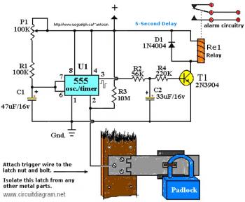
The working voltage of capacitors C1 and C2 should be increased to 25V if a 12V power source is used. A general guideline is that the operating voltage of capacitors should be at least double the supplied voltage; for...
The schematic for this project has been revised, and a new printed circuit board (PCB) has been produced. Project files for the lighthouse project are available. The project is developed for the PIC12F683 microcontroller using SourceBoost Technologies' BoostC tool...
This index is organized alphabetically by each word, excluding prepositions. For instance, the "Frost Alarm" will be listed under both "A" and "F." To efficiently locate a circuit, utilize the top index or employ your browser's search function. In...
The circuit is designed to be powered directly by a power supply, which is why it does not include a transformer, rectifier, or filter capacitors in the schematic. However, the addition of these components is possible. To operate the...

The clock circuit is constructed using a stable oscillator that consists of two inverters integrated into IC1 and a watch crystal that oscillates at 32.768 kHz. This frequency is divided by 16384 through the internal flip-flop chain of IC1,...
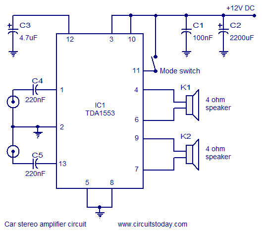
A car stereo amplifier circuit that can be used in automobiles, designed using the Class-B audio amplifier TDA1553, complete with a circuit diagram and schematics. The car stereo amplifier circuit utilizes the TDA1553, a Class-B audio amplifier known for its...