
Conducting pipe control rechargeable delay circuit
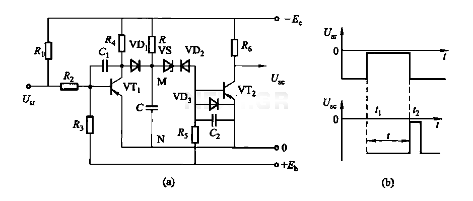
The described delay action circuit operates by utilizing transistors as switches to control the flow of current based on the input voltage levels. The conducting pipe rechargeable delay circuit is designed to maintain a negative output when a negative input is applied, indicating that the circuit is in a stable state. When the input voltage transitions to zero, the circuit switches states, effectively resetting the output to zero.
The incorporation of a potentiometer allows for fine-tuning of the delay time, providing flexibility in applications where precise timing is critical. The time interval (t) can be adjusted by changing the resistance in the circuit, which directly influences the charging and discharging characteristics of the associated capacitors. This configuration can be utilized in various electronic applications where a delay is required, such as in timing circuits, pulse generators, or in scenarios where sequential operation is necessary.
In the tube cut-off control rechargeable delay circuit, a similar principle applies, but with different operational characteristics that may involve additional components such as diodes or capacitors to enhance performance or adjust timing parameters. The discharge-type delay circuit, on the other hand, typically involves a capacitor discharging through a resistor, creating a delay before the output reaches a certain threshold.
Overall, the design of these delay circuits emphasizes the importance of transistor switching behavior and the role of passive components in defining timing characteristics, making them essential for a wide range of electronic control applications.Delay action, the instantaneous reset control circuit is divided into conducting pipe rechargeable delay circuit, tube cut-off control rechargeable delay circuit and a delay ci rcuit discharge type categories. Conducting pipe control rechargeable delay circuit Under normal circumstances, the input U., Negative potential, the transistor VTi conduction, VT2 off, the output U.. A negative potential. When [,. When zero potential, VTi off, VT2 conduction, the output goes to zero Use potentiometer. From U.. Zero potential to the U.. It becomes a zero potential time interval t is the delay time of the circuit.
Related Circuits
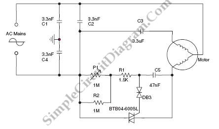
The circuit diagram below illustrates a schematic designed to control the speed of a low-power induction motor, commonly found in fans. The schematic for controlling the speed of a low-power induction motor typically incorporates several key components that work together...
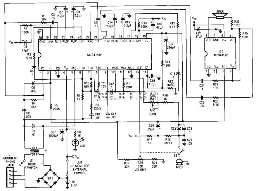
Using a Motorola MC34118 speakerphone IC, this adapter can be utilized with a standard telephone to enable speaker functionality. The device is powered from the phone line; however, it can also be powered through an external power supply if...
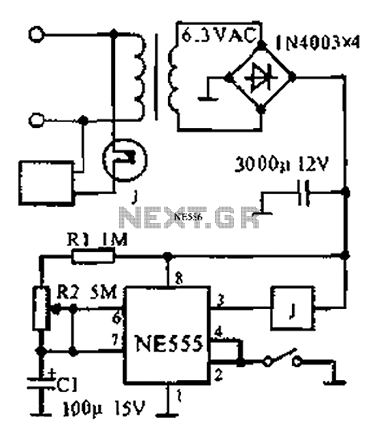
The provided information indicates that when the power supply operates between 0 to 1 hour, an AC circuit diagram is established using a 555 timer configured as a one-hour timer. The relay utilized is a J 212 IRC MR312C...
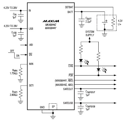
The MAX8844 lithium-ion charger integrated circuit (IC) from Maxim Semiconductors facilitates the design of a simple and efficient charger circuit for a single-cell lithium-ion battery. This charger integrates a current-sense circuit, a MOSFET pass element, thermal-regulation circuitry, and eliminates...
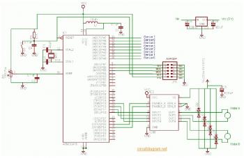
The complete electrical circuit diagram of a line follower robot is based on the ATmega16 microcontroller. This robot consists of three primary modules: the sensor module, the microcontroller module, and the DC motor module. A comprehensive tutorial, including circuit...
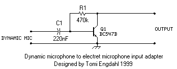
This is a simple microphone preamplifier circuit which you can use between your dynamic microphone and any equipment designed to work with an electret microphone (2 wire connection to electret capsule). This amplifier amplifies the low level signal to...