
Speed-Control for Small Asynchronous Induction Motor
The schematic for controlling the speed of a low-power induction motor typically incorporates several key components that work together to adjust the motor's operational speed effectively. The primary method of speed control in such motors involves varying the voltage or frequency supplied to the motor.
One common approach is the use of a variable resistor or potentiometer connected to a triac or a solid-state relay. The variable resistor allows the user to adjust the resistance in the circuit, which in turn alters the voltage reaching the motor. This change in voltage results in a corresponding change in the speed of the motor.
In more sophisticated designs, a pulse-width modulation (PWM) controller may be employed. This method involves switching the motor's power supply on and off at a high frequency, effectively controlling the average voltage and current supplied to the motor. The duty cycle of the PWM signal can be adjusted to vary the speed of the motor, providing a smooth and efficient operation.
Additionally, the circuit may include protective components such as fuses or circuit breakers to prevent damage due to overload conditions. Capacitors may also be present to filter out electrical noise and ensure stable operation.
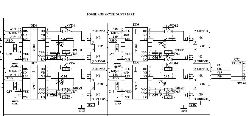
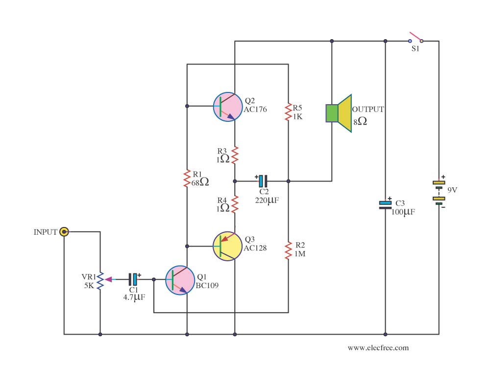
The schematic will typically include a power supply section that provides the necessary voltage to the motor, a control interface for user input, and a motor driver section that translates the control signals into motor operation. The integration of these components allows for effective speed control of low-power induction motors used in various applications, including household fans.On the circuit diagram below show us a schematic which is used to set the speed of a low-power induction motor, such as those which can be found in fan.. 🔗 External reference
Related Circuits
The primary application area for brushless direct current motors (BLDC) is in positioning systems. Brushless Direct Current (BLDC) motors are widely utilized in various positioning applications due to their high efficiency, reliability, and precise control capabilities. These motors operate without...
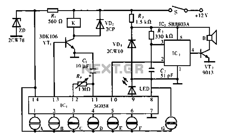
The circuit operates using an ASIC lock IC, specifically the 5C058. Pins 1 to 6 are connected outside the key switch to the positive power supply, representing six valid key inputs. To unlock, keys A through F must be...
I found this circuit in my files. I don't know where it came from, but it looks like I photocopied it from somewhere years ago. I have been told that it came from "The Robot Builder's Bonanza", by Gordan...
Integrated circuits (ICs) are commonly utilized in various audio amplifiers, particularly in compact circuits. While transistors are convenient alternatives, they offer several advantages, such as the ability to repurpose old equipment to create smaller circuits, which may be harder...
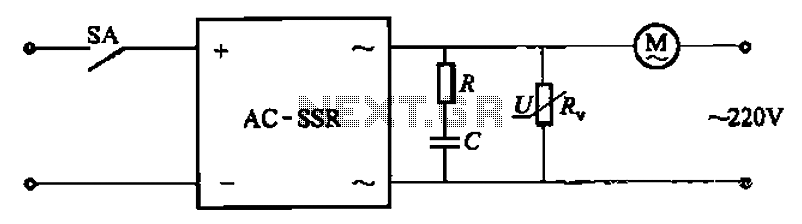
The circuit illustrated in Figure 3-13 is an RC surge absorption circuit that includes a resistor (R) and zinc oxide varistors (such as MY31, MYH12, MYH20 types, etc.), which serve as an overvoltage protection device. The resistance R is...
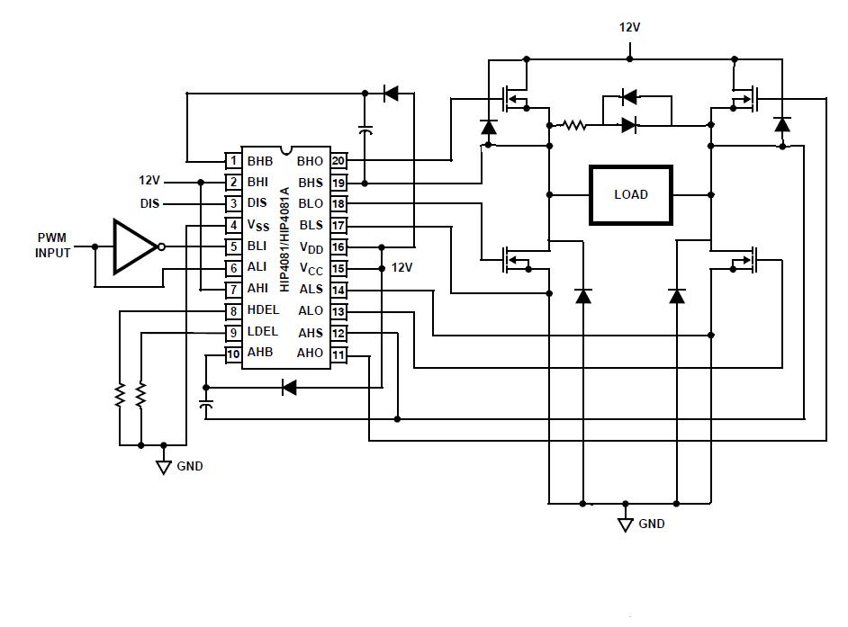
An individual is experiencing an unusual issue while utilizing an Intersil HIP4081A H-bridge driver integrated circuit (IC). The IC is connected to an Arduino microcontroller unit (MCU). The Intersil HIP4081A is a high-performance H-bridge driver designed for driving DC motors...