
Connecting an MSP430 to ADS1248 via SPI

The MSP430 microcontroller is a low-power mixed-signal processor designed for various applications, including interfacing with analog-to-digital converters (ADCs) such as the ADS1248. The SPI (Serial Peripheral Interface) protocol is commonly utilized for communication between the MSP430 and the ADC. Proper setup of the SPI peripheral is crucial for successful data transmission and reception.
To begin interfacing the ADS1248, it is essential to configure the MSP430's USCI (Universal Serial Communication Interface) module. This involves setting the clock polarity and phase, as well as the bit order. The SPI clock frequency should be set according to the specifications of the ADS1248 to ensure reliable communication. The reference voltage (REF0) must be connected correctly, as it plays a vital role in the accuracy of the ADC readings.
When writing to the ADS1248, it is imperative to follow the specific command sequence outlined in the datasheet. Each command corresponds to particular register settings that configure the ADC for desired operation modes. After configuring the registers, it is advisable to read back the register values to confirm that the settings have been applied correctly.
Using an oscilloscope to monitor the SPI communication can help identify potential issues, such as incorrect signal levels or timing problems. The data should be stable on the falling edge of the SCLK signal. If discrepancies in the expected values occur, it is necessary to verify the physical connections, ensuring that all grounds are properly connected and that there are no loose wires.
In addition, when reading the ADC results, it is critical to account for the sign extension from 24 bits to 32 bits, as the ADC output is a signed value. Failure to implement this correctly can lead to misinterpretation of the data.
Overall, careful attention to the setup of the MSP430, the configuration of the SPI communication, and the verification of connections will facilitate successful interfacing with the ADS1248 ADC, leading to accurate data acquisition for the desired application.Unfortunately we do not have a direct example for you to run on IAR at this time. However I should be able to help you get things going. What MSP430 are you using Are you mostly concerned about setting up the SPI or reading and writing the device In a previous project achieved successfully communicate with an AD7793 (Analog Device) via SPI. Now I want to change the ADC by the type of application, and chose the ADS1248. I can use the application note: sbaa121 "Interfacing the ADS1241 to MSP430 Processors" The code example you mentioned should get you started. Obviously the header definition will be different as the register set is different. Also, some of the commands/functions might not be compatible with IAR as the project was written for GCC, but it should be mostly ok.
Let me know if you have specific questions about getting things to work and I`ll be glad to help you through them. It looks like your settings are correct assuming you are connected to REF0 for your reference. Can you send me scope shots of your communication just to verify your communication is correct Have you read back your register values after setting them to make sure they are what you expect The other thing is to verify that you are actually getting good connections to the ADS1248.
Can you send me a picture of your setup Something else seems to be wrong. You should read different values (like full-scale) if you don`t have a reference voltage. I would verify my communication to the device with an oscilloscope. Your data should be stable on the falling edge of SCLK. I suspect you have communication issues. Are you able to read the registers and verify the contents have been written as you would expect Can you send me a code snippet of how you are setting up the USCI peripheral I can`t find anything obviously wrong with your code. I did notice that you do not sign extend your data when reading the result. You need to sign extend from 24 bit value to 32 bit as the data result is a signed value. I would still try to verify the communication with an oscilloscope if possible. I would also verify all my analog connections, especially ground. Can you send me a picture of your setup All content and materials on this site are provided "as is". TI and its respective suppliers and providers of content make no representations about the suitability of these materials for any purpose and disclaim all warranties and conditions with regard to these materials, including but not limited to all implied warranties and conditions of merchantability, fitness for a particular purpose, title and non-infringement of any third party intellectual property right.
TI and its respective suppliers and providers of content make no representations about the suitability of these materials for any purpose and disclaim all warranties and conditions with respect to these materials. No license, either express or implied, by estoppel or otherwise, is granted by TI. Use of the information on this site may require a license from a third party, or a license from TI. Content on this site may contain or be subject to specific guidelines or limitations on use. All postings and use of the content on this site are subject to the Terms of Use of the site; third parties using this content agree to abide by any limitations or guidelines and to comply with the Terms of Use of this site.
TI, its suppliers and providers of content reserve the right to make corrections, deletions, modifications, enhancements, improvements and other changes to the content and materials, its products, programs and services at any time or to move or discontinue any content, products, programs, or services without notice. 🔗 External reference
Related Circuits
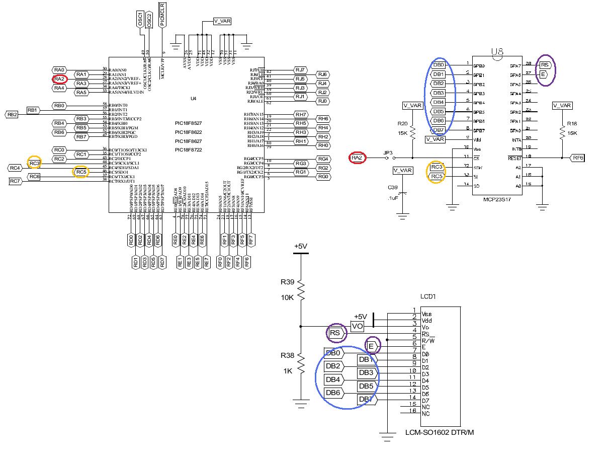
Learn to use the LCD display on the PIC 18 Explorer board with the SPI library. The SPI library will be utilized to easily display characters on the LCD. Additionally, the operation of I/O expanders will be explored. The PIC...
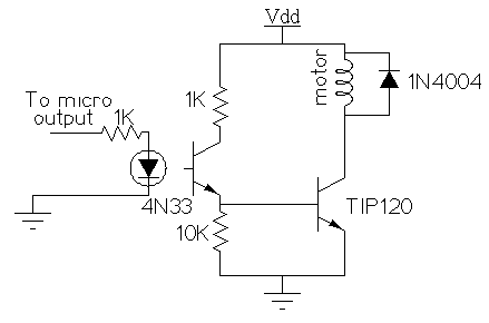
The spider prop has a straightforward mechanical setup, but its electronic configuration is more complex. It utilizes a stepper motor, which requires a controller, such as a computer or microcontroller, to operate effectively. Stepper motors do not simply turn...
Several Hall Effect sensors are available for use with a BS2 microcontroller. One intended application is to count wheel rotations. A search for a schematic to connect these sensors to the BS2 has not yielded results. Assistance in providing...
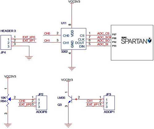
The Spartan-6 board features a 2-channel, 12-bit SPI ADC, as shown in the accompanying figure. In synchronous serial communication, a clock line (SCK in the case of SPI) is used to synchronize data transfer, with the clock being controlled...
A walkie cardiotachometer has been designed to replace the traditional method of measuring heart rate using a pulse auscultator. This device is user-friendly and consists of three main components: signal collection, data processing, and an LED display along with...
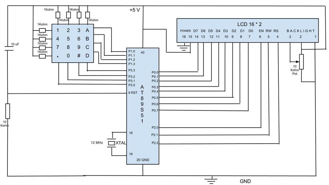
In previous posts, a schematic for interfacing a keypad and LCD using the 8051 architecture was presented. This blog post details the complete implementation of the interface using the AT89S51 microcontroller with programming in assembly language. It is assumed...