
Keypad Talking To LCD Via AT89S51
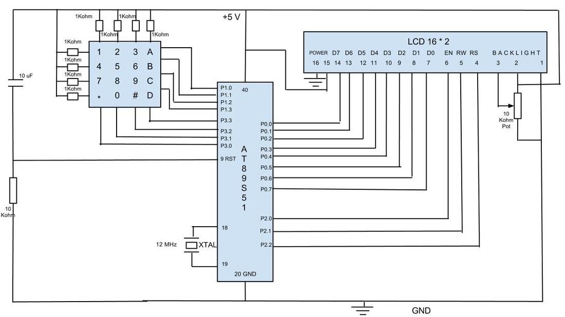
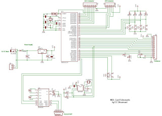
The schematic involves a typical setup for interfacing an AT89S51 microcontroller with an LCD and a keypad. The AT89S51 is an 8-bit microcontroller based on the 8051 architecture, featuring 4KB of ROM, 128 bytes of RAM, and several I/O ports. The LCD used is typically a 16x2 character display, which requires a set of control and data lines connected to the microcontroller.
The interface begins with connecting the LCD's RS (Register Select), RW (Read/Write), and E (Enable) pins to designated I/O pins on the AT89S51. The data pins D0 to D7 of the LCD are also connected to the microcontroller's I/O pins. A potentiometer is connected to the V0 pin of the LCD to control brightness, allowing the user to adjust the display contrast.
The keypad is typically a 4x4 matrix, requiring a set of rows and columns to be connected to the microcontroller. Each key press connects a specific row and column, which the microcontroller detects by scanning the rows and columns. The microcontroller's firmware is responsible for managing the scanning process, detecting key presses, and sending the corresponding character to the LCD for display.
Power supply for the entire circuit is provided at 5 volts, which is a standard operating voltage for both the AT89S51 microcontroller and the LCD. It is crucial to ensure stable voltage levels to avoid erratic behavior in the components. The assembly code uploaded to the microcontroller should include routines for initializing the LCD, handling keypad input, and updating the display accordingly.
Testing the system involves verifying that the LCD displays the correct character corresponding to the key pressed on the keypad. This comprehensive approach ensures that each component is functioning correctly and that the overall system operates as intended.In few previous post, I showed schematic for interfacing Keypad and LCD using 8051 architecture. This blog post shows complete implementation of the interface using AT89S51 Micro-controller with programming in assembly. Considering that one understands the technical background for Keypad and LCD. Now, follow the schematic given above and solder th e components on the General Purpose PCB : Note : While doing so, first solder LCD and check if it works properly by uploading the code to display the characters and the move on to Keypad phase. Doing in phases helps. Now cross check the connections and also make sure that LCD`s brightness is controllable with the pot when the system in powered using a power supply.
Supply voltage in this case was 5 Volt. Next step is to upload the code for capturing Keypad data and to display same on the LCD. I would encourage individuals to write the code on own, hence not sharing here. And after the code has been burned, place the AT89S51 on IC socket and test the system, whichever key is pressed that key should be displayed on the LCD : 🔗 External reference
Related Circuits
The reason why I am using an LCD display is because it allows me to display many characters and it doesn't need to be refreshed as 7-segment LED displays. Also, the interface requires less I/O pins. For this project,...
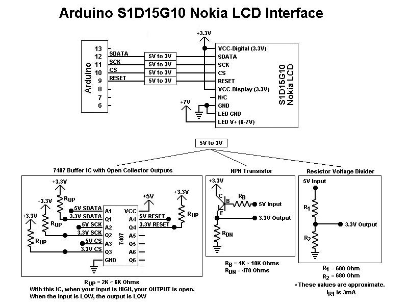
This is the first color graphic LCD display encountered. Initial assumptions were made regarding the connections, specifically that the Chip Select (CS) and RESET pins could be tied high for simplicity, based on previous experience with TTL logic. However,...
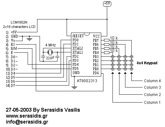
This circuit is designed for experiments using the AT90S2313 microcontroller, a 2x16 LCD display, and a 4x4 keypad. It operates with a clock based on a 4 MHz crystal, although any crystal between 1-4 MHz can be utilized. The...
The clip sync output to TTL level appears to require additional time to accommodate extra components on the board. As a temporary solution, a ZPD4.7 (4.7 V Zener Diode) should be placed between SG and ground at the power...
This is a home-made kit featuring the ATmega32 microcontroller interface. The ATmega32 controller is equipped with various features, including 32kB of in-system programmable flash memory, 1KB of EEPROM, 2KB of SRAM, a 10-bit ADC with 8 channels, an SPI...
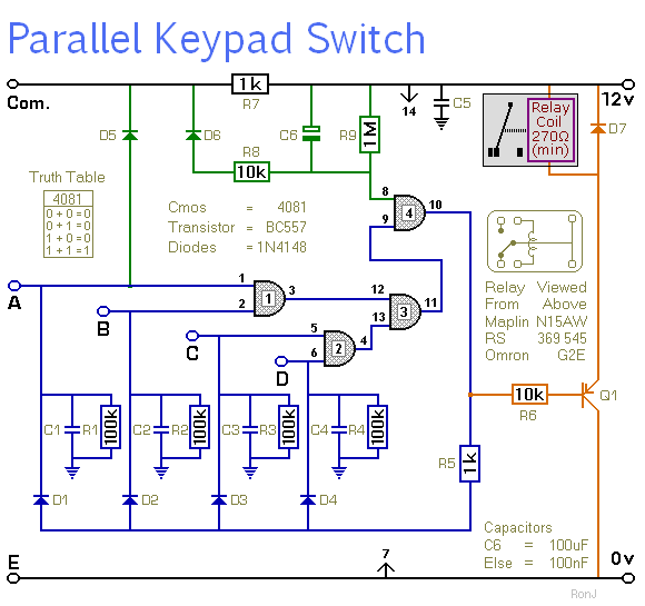
This is a universal four-digit keypad-operated switch with a unique feature. Instead of entering the security code one digit at a time, all four keypad buttons must be pressed simultaneously. This means the four numbers must be entered in...