
the design of the walkie cardiotachometer of MSP430
The schematic diagram illustrates the low-pass filtering process. Following the initial amplification stage, the heart sound signal has not yet reached the desired operational value and still contains some interference, necessitating further amplification and filtering to achieve a clear reading. The entire design emphasizes the importance of signal integrity and noise reduction to ensure accurate heart rate measurement, making it suitable for a variety of medical and fitness applications. The integration of advanced filtering techniques and amplification strategies reflects a comprehensive approach to designing a reliable cardiotachometer.We have designed a walkie cardiotachometer, it can substitute and carry on the metric classic method with pulse auscultator, etc. , it is very convenient to use. This product mainly includes three parts: Collection, data processing and LED of the signal reveal and the alarm circuit.
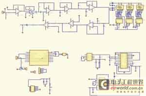
As shown in Fig. 1, turn from the detected pulse signal of the sensor into the voltage signal and send the voltagefollower, play a role in buffering, make the preceding stage and final-stage isolate, avoid mutual interference. The signal outputted is sent into the high-pass filter after pre-amplifying, by the hot electric interference of the filtration sensor, and then undergo the high frequency interference in the filtration environment of the low-pass filter.
The signal finished dealing with is sent into the final-stage and continued amplifying in order to get the little and sharp signal of the interference, this signal is sent into the one-chip computer and dealt with directly after comparator and diode rectification, in order to drive display circuit and alarm circuit. The input signal of the voltagefollower, namely the pulse sensor signal inputs from V end, the zero setting of feedback resistance, form an in-phase follower, play a role in buffering, influence of grade before and after isolating.
The function of the pulse amplifier of heart sound is to enlarge the heart sound signal of mV grade to V grade, for revealing and record and use. Because the pulse signal of the heart sound is fainter, interfere with and the noise is larger, require the loss of reducing the signal that there is high input impedance in the circuits, there are high common-mode rejection ratios Greater than 80dB Barrage jamming and noise come.
Because of in real application, external interference of signal, stability to consider amplifier, the first class amplifier can`t realize such great gain to noise temperature ratio, so the voltage amplifier is generally made up of two-stage. Among them, the preceding stage adopts the differential amplifying circuit of negative feedback, in order to improve the rejection ratio of the common mode signal.
This partial key is how to inhibit various noises, avoid letting the noise scurry into the circuit of final-stage. So in the system, adopt the instrument amplifier AD620 of low power loss based on dual operational amplifier circuit as the pre-amplifier of pulse signal of heart sound.
In order to prevent producing the nonlinear distortion so that the common-mode rejection ratio of the damage circuit, this partial magnification should not be too high, it is about 1000 times to choose as. In this design, the signal frequency is lower, between 0. 78- 3. 33Hz, so the key designed as this circuit to the electric-wave filter. First of all, will pass the high-pass filter of one 0. 5Hz, in order to leach the hot electric interference of the sensor, then pass another low-pass filter to interfere with with the overwhelming majority of the filtration heart sound signal.
In realizing the circuit, it is already very difficult for the ordinary electric-wave filter to filter such a low signal, so adopt the gain to noise temperature ratio to change more smooth electric-wave filter of Bart`s fertile Sri Lankan in this design. Among them, the high pass is the electric-wave filter of second order Bart`s fertile Sri Lankan, it is the alpha cut frequency, for the fertile electric-wave filter then of Bart of 5Hz to be low-pass.
Fig. 3 is the schematic diagram of the low-pass filtering. The heart sound signal is after the preceding stage is amplified, the range has not reached the ideal using value yet, and there is certain interference, so need t 🔗 External reference
Related Circuits
Colpitts Oscillator tutorial and the theory behind the design of the Colpitts Oscillator, which uses an LC oscillator tank circuit to generate sine waves. The Colpitts oscillator is a type of electronic oscillator that utilizes a tank circuit composed of...

An audio filter is positioned at the input of each audio integrated circuit (IC) chip to filter the audio signal intended for speakers. A low-pass filter is utilized for the woofer, while a high-pass filter is employed for midrange...
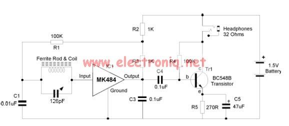
The MK484 AM radio circuit offers a comprehensive solution featuring an RF amplifier, detection, and an automatic gain control (AGC) circuit. It requires only a few external components to achieve high-quality AM tuning. The circuit has an input impedance...
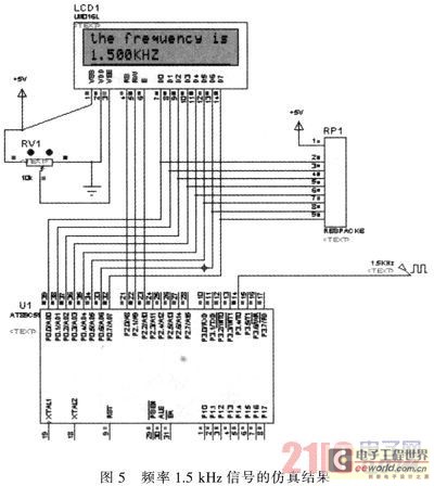
The primary function of the frequency counter is to measure the frequency and cycle of a signal. Its applications span a wide range, extending beyond simple instrument measurements to areas such as education, scientific research, high-precision instrument measurement, and...
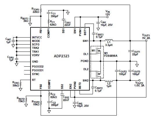
The ADP2323 DC-DC converter is designed to deliver two output voltages with specified maximum output currents. The first channel provides a 5-volt output with a maximum current of 2 Amperes, while the second channel supplies 1 volt with a...
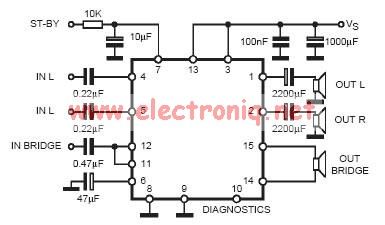
In practical applications, a series resistance must always be included. This component serves the dual purpose of limiting the current at pin 7 and smoothing the ON/OFF transitions during standby. In electronic circuits, particularly those involving integrated circuits (ICs) or...
Warning: include(partials/cookie-banner.php): Failed to open stream: Permission denied in /var/www/html/nextgr/view-circuit.php on line 713
Warning: include(): Failed opening 'partials/cookie-banner.php' for inclusion (include_path='.:/usr/share/php') in /var/www/html/nextgr/view-circuit.php on line 713