
Connecting Infrared Thermometer MLX90614
The MLX90614 infrared thermometer operates through the principle of non-contact temperature measurement, utilizing infrared radiation emitted by objects. This sensor is particularly advantageous in applications where traditional thermometers may not be feasible, such as measuring the temperature of moving objects or in hazardous environments.
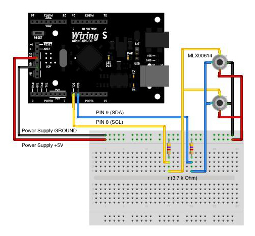
To interface with the MLX90614, the preferred method is through I²C communication, which allows for a simplified wiring setup and the ability to connect multiple devices on the same bus. The I²C protocol operates with two wires: Serial Data Line (SDA) and Serial Clock Line (SCL). For the Wiring v1 board, the I²C pins are designated as 0 for SCL and 1 for SDA, while for the Wiring S board, they are 8 for SCL and 9 for SDA.
The I²Cmaster library is essential for effective communication with the MLX90614. This library is tailored to support the specific requirements of the MLX90614, particularly addressing the repeated start condition that the standard Wire library does not accommodate. Upon installation of the I²Cmaster library, the sensor can be initialized and configured to read temperature data.
The provided code initializes the serial communication at a baud rate of 9600 and sets up the I²C bus. It includes a loop that continuously reads the temperature from the MLX90614, converts the readings from Celsius to Fahrenheit, and outputs both values to the serial monitor. The temperature reading is processed by gathering high and low byte data from the sensor, applying necessary conversions, and adjusting for resolution.
Overall, the MLX90614 sensor, when interfaced correctly through the I²C protocol using the I²Cmaster library, provides accurate and reliable temperature readings, making it a valuable tool for various applications in electronics and automation.MLX90614 is a very useful infrared thermometer (no contact needed) that gives you the average temperature reading of all objects in the view range. In addition to it`s principal temperature reading function, it can be used for movement or even presence detection.
There are two ways of interfacing this sensor, through PWM communication or SMBus (TWI or I ²C) communication. I wasn`t able to get the first one working, so tried SMBus I ²C that is not easier to code but gives you some advantages over PWM. Through I ²C you can connect over 127 devices using just two Wiring pins and also, in this specific sensor (MLX90614) you get better resolution readings.
Wiring comes with a special library for interfacing I ²C devices (wire library) but unfortunately this library is not compatible with MLX90614 because it doesn`t support the use of the repeated start function (if you want to read further about this issue check this link ). So, we are going to use the I ²Cmaster library that has been modified by the guys at bildr. blog for working properly with the Wiring board. The first thing that has to be done is to download and instal the the I ²Cmaster library. As I said before, were using a version modified by the guys at bildr. blog. Once you have the library installed, you can use the following setup diagram and code for reading temperature from one MLX90614 connected to the TWI pins (on the Wiring v1 board 0 (SCL) and 1 (SDA) and on Wiring S board 8 (SCL) and 9 (SDA).
Both (diagram and code) are based on the Is it hot Arduino + MLX90614 IR Thermometer bildr. blog post. /* * Infrared Thermometer MLX90614 * by Jaime Patarroyo * based on `Is it hot Arduino + MLX90614 IR Thermometer` by bildr. blog * * Returns the temperature in Celcius and Fahrenheit from a MLX90614 * Infrared Thermometer, connected to the TWI/I ²C pins (on the Wiring v1 * board 0 (SCL) and 1 (SDA) and on Wiring S board 8 (SCL) and 9 (SDA).
*/ #include
fahrenheit = (celcius*1. 8) + 32; // Converts celcius into Fahrenheit // and stores in Fahrenheit variable. Serial. print("Celcius: "); // Prints both readings in the Serial Serial. println(celcius); // port. Serial. print("Fahrenheit: "); Serial. println(fahrenheit); delay(1000); // Wait a second before printing again. } float temperatureCelcius(int address) { int dev = address; int data_low = 0; int data_high = 0; int pec = 0; // Write i2c_start_wait(dev+I2C_WRITE); i2c_write(0x07); // Read i2c_rep_start(dev+I2C_READ); data_low = i2c_readAck(); // Read 1 byte and then send ack. data_high = i2c_readAck(); // Read 1 byte and then send ack. pec = i2c_readNak(); i2c_stop(); // This converts high and low bytes together and processes temperature, // MSB is a error bit and is ignored for temps.
double tempFactor = 0. 02; // 0. 02 degrees per LSB (measurement // resolution of the MLX90614). double tempData = 0x0000; // Zero out the data int frac; // Data past the decimal point // This masks off the error bit of the high byte, then moves it left // 8 bits and adds the low byte. tempData = (double)(data_high & 0x007F) << 8) + data_low); tempData = (tempData * tempFactor)-0. 01; float celcius = tempData - 273. 15; // R 🔗 External reference
Related Circuits

A unified thermometric controller that can be programmed with simple scripts, integrating the "classic" thermometer/controller pair. You can build a variety of simple machines with the same hardware and a different script: a charting thermometer, a vending machine that...
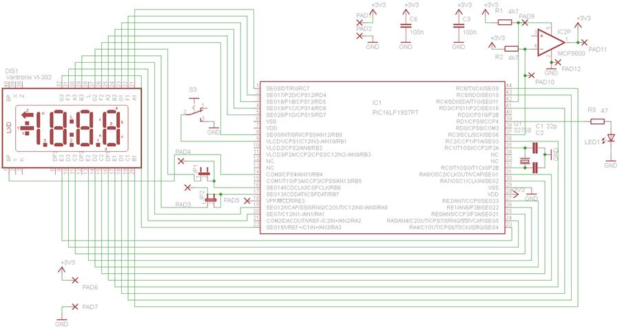
This circuit is centered around the PIC16LF1937 microcontroller, which is essentially a compact computer integrated into a single chip, encompassing RAM, EEPROM, I/O ports, and a CPU. When purchased, the chip is unprogrammed, necessitating the compilation of source code...

To prevent the failure of electric contact pressure thermometer contacts due to singeing, it is advisable to enhance the contacts, as illustrated in Fig. 11-60. Specifically, the output termination table for DC control utilizes two two-way thyristors or a...

This circuit consists of two parts, the first part will transmit a signal, and the second part will detect that signal and trigger a relay. To adjust the circuit, hold down S1 while pointing LED1 at the receiver. Adjust...
The following is a method to allow day and night detection using Infrared/Visible light sensitive phototransistors and a simple LM339 voltage comparator circuit. A phototransistor is mounted between the rails so that it is covered by the train as...
This transmitter utilizes a 5089 DTMF generator chip along with a keypad to produce DTMF signals, which are then modulated onto an infrared (IR) light beam emitted from an IR LED. The circuit employs a 3.579-MHz TV burst crystal...