
Infrared Alarm

The circuit described features a basic infrared (IR) communication system, which is divided into a transmitter and a receiver section. The transmitter is built around an LED (LED1), which emits infrared light when activated. The second part of the circuit includes a photodiode or phototransistor that acts as the receiver, detecting the IR signal transmitted by LED1.
In the transmitter section, when the switch S1 is pressed, it completes the circuit, allowing current to flow through LED1. The LED emits infrared light, which can be directed towards the receiver. The intensity of the emitted light can be adjusted using a variable resistor (R6). This adjustment is crucial for ensuring that the signal strength is adequate for reliable detection by the receiver.
The receiver section is designed to sense the IR light emitted by the transmitter. When the photodiode or phototransistor detects the IR light, it generates a corresponding electrical signal. This signal is used to trigger a relay, which can be employed to control larger loads or provide an output indication.
To optimize the performance of the circuit, especially in terms of range, it is recommended to use a high-output LED for LED1. This choice enhances the transmission distance, allowing the signal to be detected from further away. However, it is important to note that ambient bright light can interfere with the operation of the receiver, potentially causing it to fail to respond to the transmitter's signal. Therefore, careful placement and adjustment of the circuit components are necessary to mitigate this issue.
The use of printed circuit boards (PCBs) for this design simplifies the assembly process, providing a structured layout for the components, which aids in minimizing errors during construction and ensures reliable operation. The PCBs can be designed to accommodate all necessary components, including the LED, relay, resistors, and any additional supporting circuitry required for optimal performance.This circuits consist of two parts, the first part will transmit a signal, and the second part will detect that signal and trigger a relay.To adjust the circuit, hold down S1 while pointing LED1 at the receiver. Adjust R6 until you hear the relay click. You can increase range by using a high output LED for LED1. Bright light will stop the receiver from responding to the transmitter. You can use the designed PCBs to build the circuit simply: 🔗 External reference
Related Circuits

This circuit functions as a flood alarm using several bipolar transistors. When liquid comes into contact with the probes, a leakage current biases Q1, Q2, and Q3 (configured as a direct current-coupled amplifier) into conduction, thereby activating the relay....
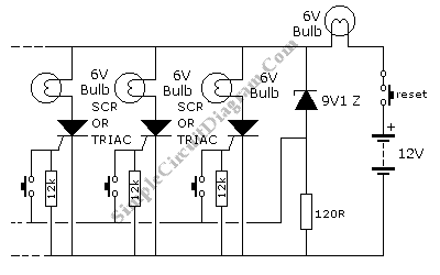
This is a quiz bell/alarm circuit designed to indicate the fastest finger first. The circuit includes one bulb for the quiz master and one for each contestant. The bulbs illuminate when a button is pressed. The cathode of the...
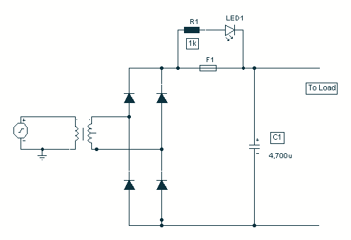
It came to me in a flash. A simple way to see if a fuse has blown without removing it from its holder. Its not often you can design a circuit using just two components, but with just one...

This circuit is a slight modification of a previous design. In the earlier version, the switch needed to be held down for the entire duration of the music playback. In this updated circuit, pressing the push button once charges...
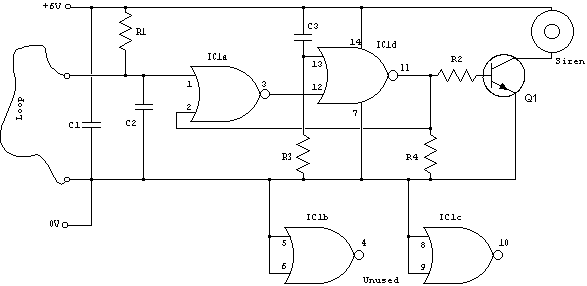
The loop can consist of any type of hookup wire, with a maximum resistance of approximately 90K ohms. Utilizing very thin wire (such as 40AWG) will create a highly sensitive trip wire; however, this will reduce the distance over...
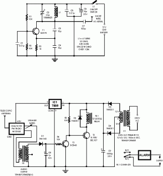
This circuit is a wireless car alarm system constructed using two modules: a transmitter module and a receiver module. It operates on FM radio waves and is suitable for vehicles with a power supply of 6-12VDC. A voltage stabilizer...